Energy absorption structure optimization method taking expected force response process as target

An energy-absorbing structure and optimization method technology, applied in the field of traffic safety, can solve problems such as unreasonableness, uncertainty of optimization results, influence of optimization results, etc.

Pending Publication Date: 2021-04-09
西北工业大学太仓长三角研究院 +1
View PDF1 Cites 0 Cited by
  • Summary
  • Abstract
  • Description
  • Claims
  • Application Information

AI Technical Summary

Problems solved by technology

One is the equivalent static load method proposed in the article "Technical overview of the equivalent static loads method for non-linear static response structural optimization" published in "Structural and Multidisciplinary Optimization" by Gyung-Jin Park, which effectively reduces the amount of calculation. It is possible to use traditional optimization methods, but it is difficult for multiple static loads to be equivalent to the actual impact load conditions, and the accuracy of dynamic analysis results is poor, which affects the optimization results
The second is the hybrid cellular automata method for structural crashworthiness design in the article "Topometry optimization for crashworthiness design using hybrid cellular automata" published by Andrés Tovar in "International Journal of Vehicle Design". This method uses display dynamics analysis, The analysis results are accurate, but the "energy uniform distribution criterion" adopted is irrational, and the "area energy uniform distribution criterion" is too dependent on human prior experience, and the optimization results are uncertain

Method used


Image

  • Energy absorption structure optimization method taking expected force response process as target
  • Energy absorption structure optimization method taking expected force response process as target
  • Energy absorption structure optimization method taking expected force response process as target

Examples


Embodiment 1

[0085]This embodiment is a method of optimizing the ability to measure the desired force response process, and the specific process is:

[0086]Step 1, establish the original finite element model of the impact of thin-walled tube:

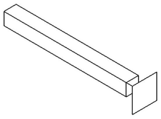
[0087]The original finite element model of the impact is established based on the structural characteristics of the impact thin-walled tube and the rigid impact plate. Such asfigure 1 As shown, the structural feature of the impact thin-walled tube and the rigid impact plate is divided into two parts, and a portion is a thin-walled tube having a square cross section, the thin wall tube is 100 mm, and the length is 1000 mm, the wall thickness is 3.0. mm; another part is a square rigid impact board with a side length of 200 mm. The rigid impact plate is located at one end of the thin wall tube and causes the center line of the thin-walled tube to coincide with the geometric center of the rigid impingement plate; the end surface of the thin wall tube and the surfa...

Embodiment 2

[0139]This embodiment is a method of optimizing the ability to measure the desired force response process, and the specific process is:

[0140]Step 1, establish the original finite element model of the impact of thin-walled tube:

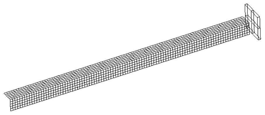
[0141]The original finite element model of the impact is established based on the structural characteristics of the impact thin-walled tube and the rigid impact plate. Such asFigure 8 withFigure 9 As shown, the structural feature of the impact thin-walled tube and the rigid impact plate is divided into two parts, and a portion is a thin-walled tube having a square cross section, the thin wall tube is 100 mm, and the length is 1000 mm, the wall thickness is 3.0. MM; another part is a rectangular rigid impact plate at one end of the thin wall tube, which is 880 mm long and 400 mm wide.

[0142]The thin-walled tube is located at one end of the rigid impingement plate and intersects the geometric center line of the thin-walled cross section to the center line in the ...

Embodiment 3

[0190]This embodiment is a method of optimizing the ability to measure the desired force response process, and the specific process is:

[0191]Step 1, establish the original finite element model of the impact of thin-walled tube:

[0192]The original finite element model of the impact is established based on the structural characteristics of the impact thin-walled tube and the rigid impact plate. Such asFigure 8 withFigure 9 As shown, the structural feature of the impact thin-walled tube and the rigid impact plate is divided into two parts, and a portion is a thin-walled tube having a square cross section, the thin wall tube is 100 mm, and the length is 1000 mm, the wall thickness is 3.0. MM; another part is a rectangular rigid impact plate at one end of the thin wall tube, which is 880 mm long and 400 mm wide.

[0193]The thin-walled tube is located at one end of the rigid impingement plate and intersects the geometric center line of the thin-walled cross section to the center line in the ...


PUM


Abstract

The invention discloses an energy absorption structure optimization method taking an expected force response process as a target, and the method comprises the steps: setting a proper expected force response curve, continuously updating the value of a target function in an optimization process in an iteration mode so as to obtain a new finite element model, and enabling an actual force response curve of a structure to be gradually close to the expected force response curve, and improving the energy absorption capacity of the structure. According to the method, the deformation mode of the thin-walled tube can be changed, low-energy-absorption Euler deformation is changed into high-energy-absorption progressive buckling deformation, and multiple energy absorption evaluation indexes can be improved at the same time. The optimized actual force response curve of the thin-walled tube is closer to the expected force response curve. The energy absorption component obtained through the method can generate an ideal deformation mode, more impact kinetic energy is dissipated, and great guiding significance is achieved for design of energy absorption devices of various vehicles.

Description

Technical field[0001]The present invention belongs to the technical field of traffic safety, and more particularly to a suitable method optimization method for the target of the desired force response process.Background technique[0002]Security is the most basic requirement in the design of the vehicle design. In recent years, with the development of the transportation industry, collision accidents have become a prominent issue affecting the safety of the occupant. The thin-walled metal structure has been widely used in the capability structure of the automobile and the aviation industry due to its lightweight, manufacturability and good impact resistance. When a collision occurs in a vehicle or aircraft, the suction structure is safe to ensure the safety of the impact energy by plastic deformation. The capability capability of the thin-walled metal structure is closely related to its deformed mode. The ideal deformed mode is gradually buckling, which can generate more pleated deform...

Claims


Application Information

Patent Timeline
Patent Type & Authority Applications(China)
IPC IPC(8): G06F30/23G06F30/17G06F30/15G06F119/14G06F111/06G06F111/04
CPCG06F30/23G06F30/17G06F30/15G06F2119/14G06F2111/04G06F2111/06
Inventor 安伟刚王世根韩煦
Owner 西北工业大学太仓长三角研究院
Why Eureka
Try Eureka