Power Input Device with Current Pulse Multiplier Transformer to Reduce Harmonic Currents in Converter/Inverter Circuits and Devices, and Method of Making the Same

a transformer and transformer technology, applied in the field of transformer circuits and transformer circuits, can solve the problems of high frequency of harmonic currents, undesirable effects of device/circuit operation, and harmonic currents associated with alternating current power sources

Active Publication Date: 2011-08-04
HOWARD INDS
View PDF7 Cites 16 Cited by
  • Summary
  • Abstract
  • Description
  • Claims
  • Application Information

AI Technical Summary

Benefits of technology

Disclosed are a plurality of three phase power input devices and variable frequency drive (VFD) systems, which include a three phase transformer circuit that is designed with an output winding phase angle scheme that yields advanced harmonic current quashing (AHQ) within the power input device and / or the VFD system based on an increase in the number of current pulses (pulse number) in the power input to components of the VFD. The transformer circuits comprise a secondary winding scheme that provides a plurality of secondary winding output leads to power each of multiple converter / inverter components of the connected VFD. Each of the three phase transformer outputs coupled to a respective converter / inverter has a unique / different phase angle from the phase angle of each one of the other three phase transformer outputs that are applied to the other converter / inverter components of the VFD. The resulting power input device and / or VFD system exhibits a substantial increase in the pulse number, with a magnitude of greater than two times (2×) (and up to six times (6×)) the number of converter / inverter modules in the VFD. With this significant increase in the pulse number, the power input device and / or VFD system also exhibits a corresponding substantial decrease in the harmonic currents associated with the power inputs to the VFD and the VFD system.

Problems solved by technology

When powering certain types of electrical devices and / or circuits, such as a variable frequency drive (VFD) utilized to supply power to nonlinear loads, such as large pumping systems in the offshore petroleum industry, the occurrence of harmonic currents associated with the alternating current (AC) power source presents an undesirable effect in the operations of the device / circuit.
Additionally, the VFD systems themselves often present a nonlinear load to the AC power source, and thus manifest / exhibit a high incidence of harmonic currents in the power system.

Method used


Image

  • Power Input Device with Current Pulse Multiplier Transformer to Reduce Harmonic Currents in Converter/Inverter Circuits and Devices, and Method of Making the Same
  • Power Input Device with Current Pulse Multiplier Transformer to Reduce Harmonic Currents in Converter/Inverter Circuits and Devices, and Method of Making the Same
  • Power Input Device with Current Pulse Multiplier Transformer to Reduce Harmonic Currents in Converter/Inverter Circuits and Devices, and Method of Making the Same

Examples


first embodiment

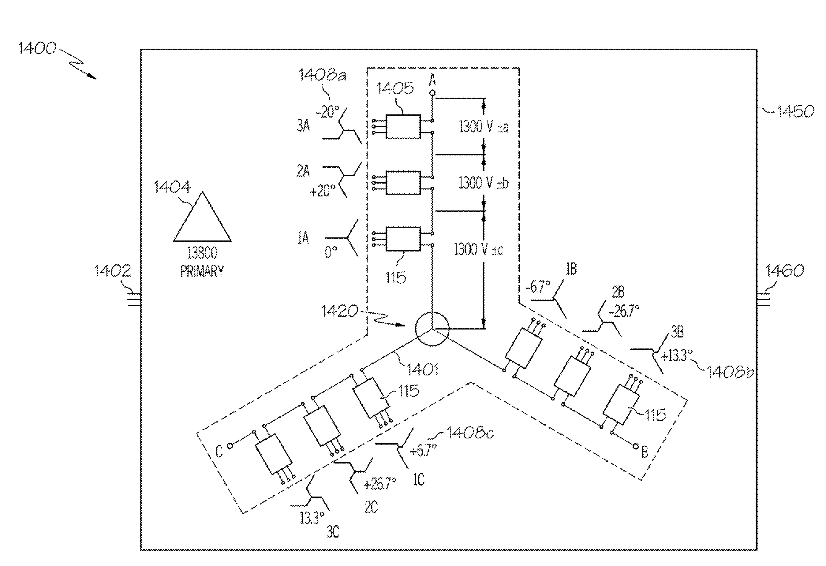
A first embodiment provides a power input device comprising: an advanced harmonic current quashing (AHQ) or current pulse multiplier (CPM) three-phase transformer having: a magnetic core having a three phase configuration; a primary winding placed around the magnetic core and having three primary winding leads to which a three phase power supply can be connected; and a plurality of secondary windings placed around the magnetic core in a predetermined winding turns configuration to generate a plurality of three phase outputs, where each three phase output of the plurality of three phase outputs has a different phase angle from all other three phase outputs, with each unique phase angle associated with a three phase output of a corresponding secondary winding being determined based on the winding turns configuration utilized for the corresponding secondary winding. The power input device further comprises an arrangement of three-phase to single-phase electrical components, with a thre...

second embodiment

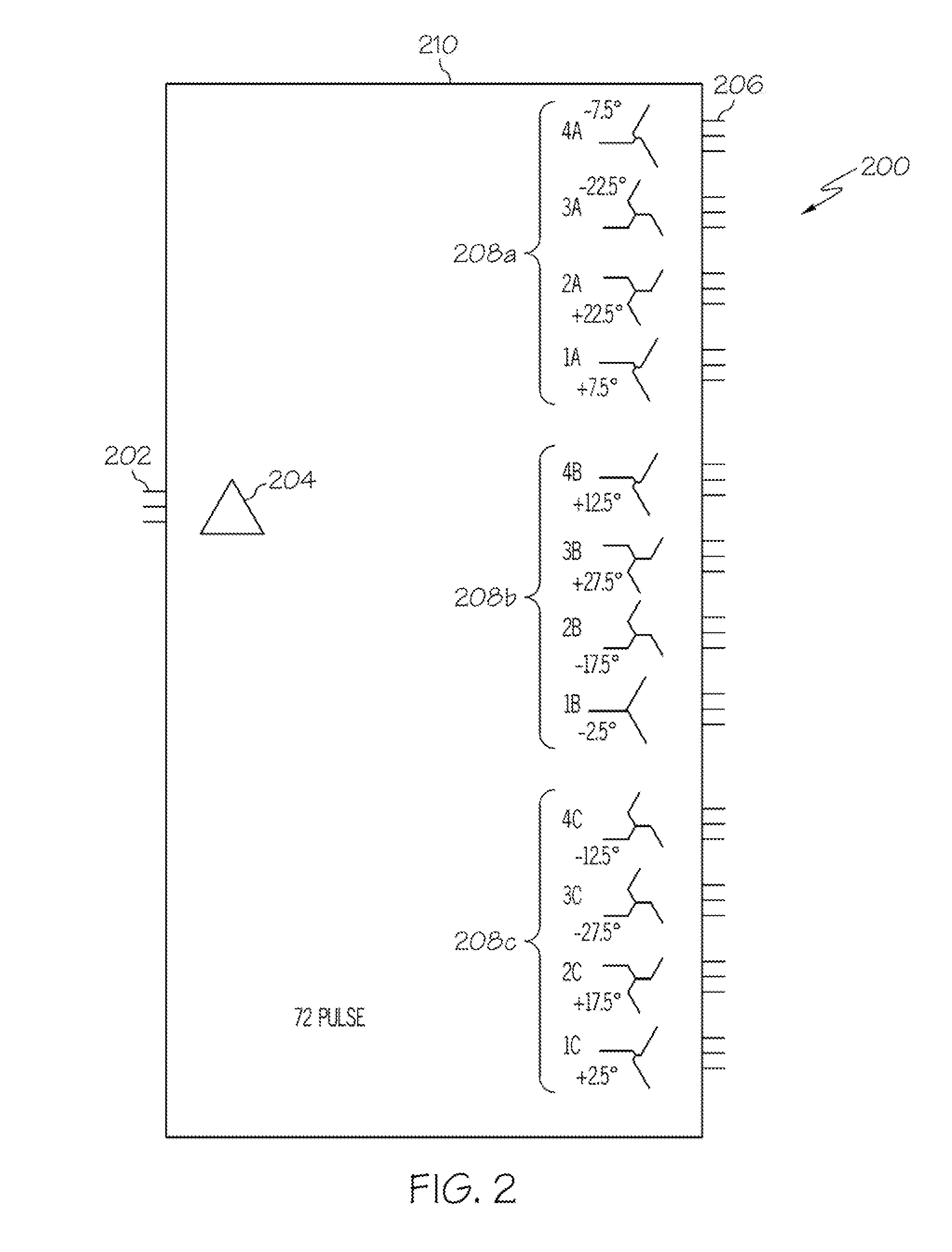
A second embodiment provides a system comprising: an electrical device having three legs connected at an electrical neutral, with each leg extending from the electrical neutral to provide one of three outputs, wherein each leg comprises N serially-connected components that each comprises a three phase input and a single phase output; and an AHQ / CPM transformer comprising: a plurality of secondary windings placed around the limb(s) of the magnetic core in a predetermined winding turns configuration to generate three sets of N three phase outputs that are respectively coupled to the N serially-connected components of each leg of the electrical device, where each three phase output of the plurality of three phase outputs has a different phase angle from all other three phase outputs. Each unique phase angle associated with a three phase output of a corresponding secondary winding is determined based on the winding turns configuration utilized for the corresponding secondary winding. Th...


PUM

PropertyMeasurementUnit
output voltageaaaaaaaaaa
voltageaaaaaaaaaa
voltageaaaaaaaaaa

Abstract

A power supply device comprising an advanced harmonic current quashing (AHQ) and current pulse multiplier (CPM) (AHQ/CPM) three-phase transformer having: a primary winding placed around a magnetic core and having three primary winding input leads to connect a three phase power supply; and a plurality of secondary windings placed around the magnetic core in a predetermined winding turns configuration to generate a plurality of three phase outputs, where each three phase output of the plurality of three phase outputs has a different phase angle from all other three phase outputs, with each unique phase angle associated with a three phase output of a corresponding secondary winding being determined based on the winding turns configuration utilized for the corresponding secondary winding. A variable frequency drive (VFD) having 3N converters/inverters coupled to the secondary windings outputs exhibit substantially reduced harmonic currents and a current pulse number of greater than 6N.

Description

BACKGROUND OF THE INVENTION1. Technical FieldThe present invention relates generally to electrical circuits and in particular to transformer circuits. Still more particularly, the present invention relates to transformer circuits and designs that reduce harmonic currents in three phase applications.2. Description of the Related ArtWhen powering certain types of electrical devices and / or circuits, such as a variable frequency drive (VFD) utilized to supply power to nonlinear loads, such as large pumping systems in the offshore petroleum industry, the occurrence of harmonic currents associated with the alternating current (AC) power source presents an undesirable effect in the operations of the device / circuit. The amount of harmonic currents present in a conventional VFD system (depicted in FIG. 1) is typically directly correlated to the pulse number (number of current pulses) associated with the power input to the converter sections of the VFD. In turn, with conventional VFD designs,...

Claims


Application Information

Patent Timeline
Patent Type & Authority Applications(United States)
IPC IPC(8): H01F30/12H01F7/06
CPCH02M7/49Y10T29/49071H01F30/12H02M1/12H02M5/14
Inventor OWEN, DONALD W.
Owner HOWARD INDS
Why Eureka
Try Eureka