
System for Removing a Display Unit From a Multi Panel Display

a multi-panel display and display unit technology, applied in the field of multi-panel display systems, can solve the problems of difficult removal and replacement of display units b>102/b> that are damaged or need service, and can be relatively bulky

Active Publication Date: 2011-08-04
PRYSM SYST INC
View PDF7 Cites 28 Cited by
  • Summary
  • Abstract
  • Description
  • Claims
  • Application Information

AI Technical Summary

Benefits of technology

[0010]One advantage of the present invention is that a display unit can be removed from a tiled display wall with minimal risk of damaging delicate external components of the display unit. Another advantage of the present invention is that display units that have been moved to create adequate clearance for access to another display unit can be quickly and repeatably returned to their original locations without the need for additional position adjustment.
is that a display unit can be removed from a tiled display wall with minimal risk of damaging delicate external components of the display unit. Another advantage of the present invention is that display units that have been moved to create adequate clearance for access to another display unit can be quickly and repeatably returned to their original locations without the need for additional position adjustment.

Problems solved by technology

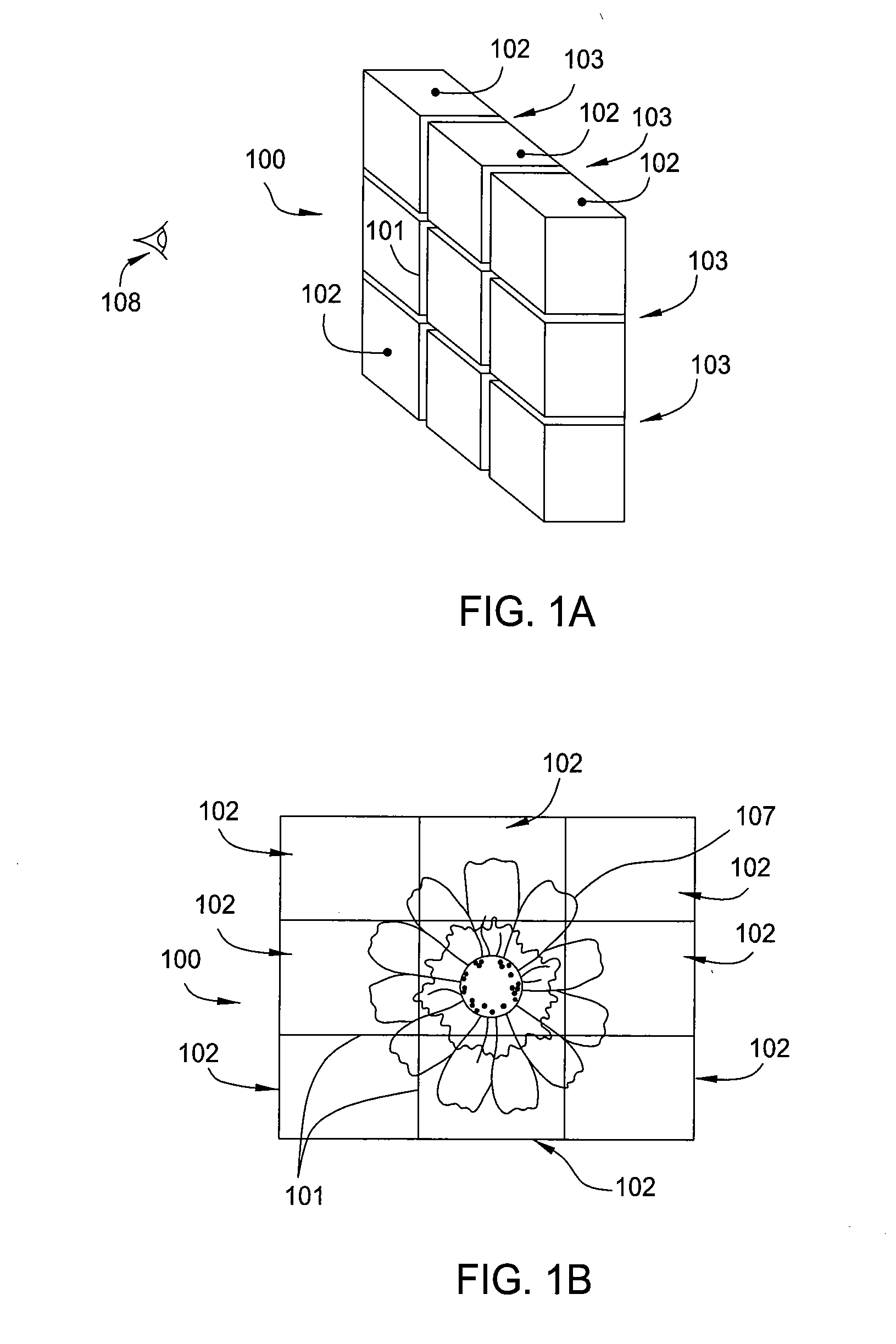
An issue with tiled displays is that the gap present between the constituent display units can produce a grid pattern visible to the viewer.
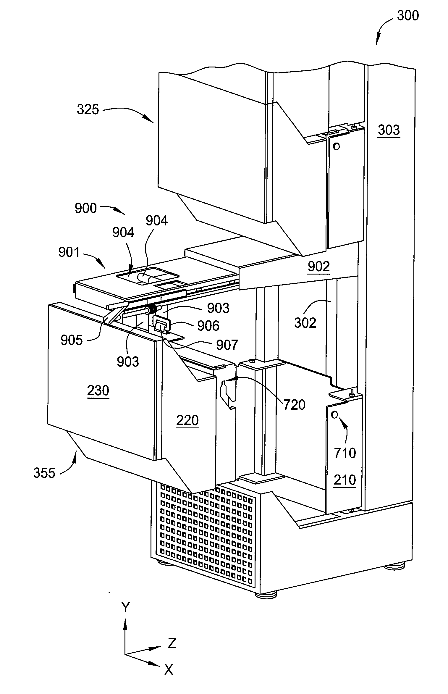
Display units 102 for a typical tiled display can be relatively bulky, heavy, and include delicate external components, such as the precisely shaped glass panels often used as an image forming surface.
Consequently, removal and replacement of a display unit 102 that is damaged or needs service is problematic due to the risk of damaging additional display units 102 while removing the damaged unit.

Method used


Image

  • System for Removing a Display Unit From a Multi Panel Display
  • System for Removing a Display Unit From a Multi Panel Display
  • System for Removing a Display Unit From a Multi Panel Display

Examples


Embodiment Construction

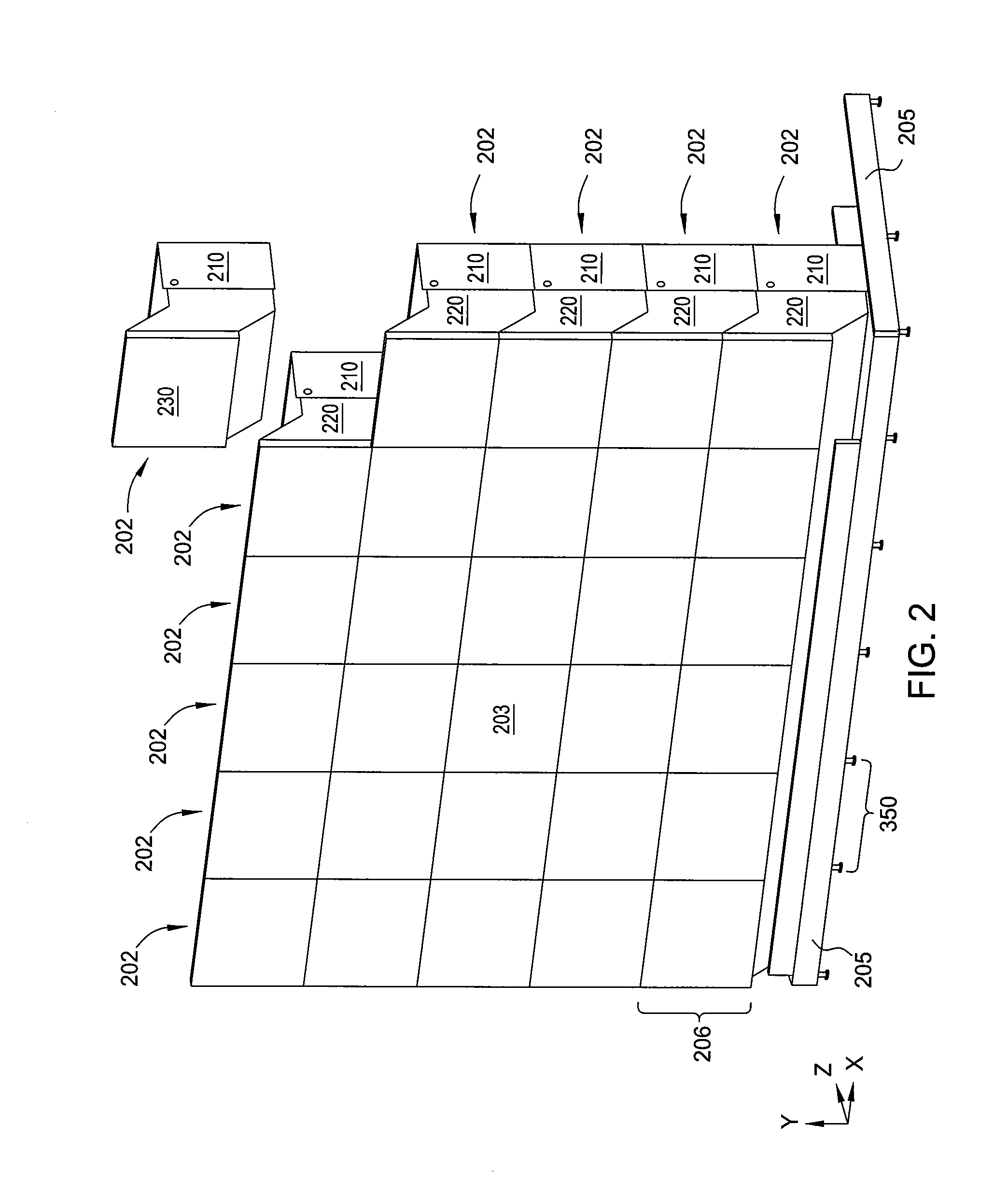
[0025]FIG. 2 illustrates a multi-panel display 200 according to various embodiments of the invention. Multi-panel display 200 includes a plurality of display units 202 assembled to form a display surface 203. In some embodiments, display surface 203 is a planar viewing surface, while in other embodiments, display surface 203 may be curved. For purposes of description, one of display units 202 in FIG. 2 is shown positioned above multi-panel display 200 prior to installation. Multi-panel display 200 is depicted as a six-tile by five-tile array, i.e., six columns of five display units, but any multi-tile display falls within the scope of the invention. In some embodiments, multi-panel display 200 includes a base structure 205 configured to provide stability against tipping and a means for seismic restraint. In such embodiments, base structure 205 is precisely leveled and a first row 206 of display units 202 are mechanically coupled thereto base structure 205 so that first row 206 forms...


PUM


Abstract

A lift system removes a display unit or components thereof from a tiled display wall in a way that minimizes the risk of damaging the removed display unit and other display units in the tiled display wall. A lifting structure is configured to selectively lift one or more display units away from the desired display unit when the lifting structure is raised by a vertical motion actuator. The lifting structure is further configured to be free to rotate slightly about a vertical axis when lifting the display units, so that the lifted display units are not constrained to purely vertical translation when lifted away from the desired display unit.

Description

CROSS-REFERENCE TO RELATED APPLICATIONS[0001]This application claims the priority benefit of the U.S. Provisional Patent Application filed on Jan. 29, 2010 and having Ser. No. 61 / 299,914. The subject matter of this related application is hereby incorporated herein by reference.BACKGROUND OF THE INVENTION[0002]1. Field of the Invention[0003]Embodiments of the present invention relate generally to multi-panel display systems and, more specifically, to apparatus for removing a display unit from a such systems.[0004]2. Description of the Related Art[0005]Electronic display systems are commonly used to display information from computers and other sources. Typical display systems range in size from small displays used in mobile devices to very large displays that are used to display images to thousands of viewers at one time. Tiled display walls provide a large-format environment for presenting large high-resolution images by synchronizing and coupling the output from multiple distinct im...

Claims


Application Information

Patent Timeline
IPC IPC(8): B66F11/00B66C23/18B66F3/08B66F3/36
CPCB65G57/302G06Q30/02G09F9/3026G09G2300/026G09F9/33
Inventor BONN, BRIANINORI, DAVIDMISSO, NIGEL F.
Owner PRYSM SYST INC
Learn More