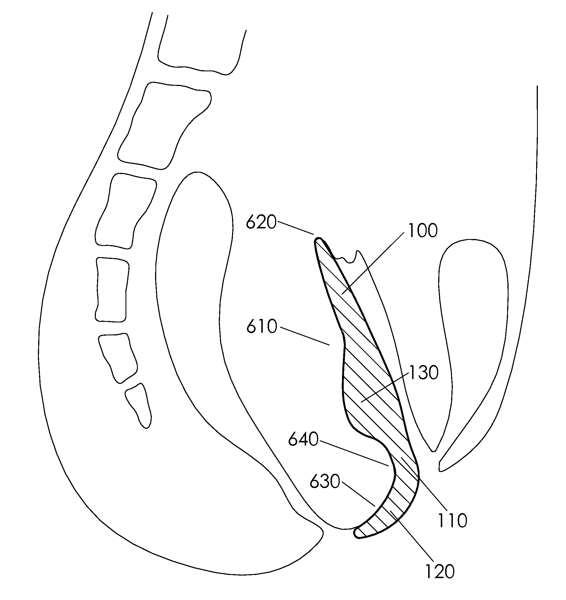
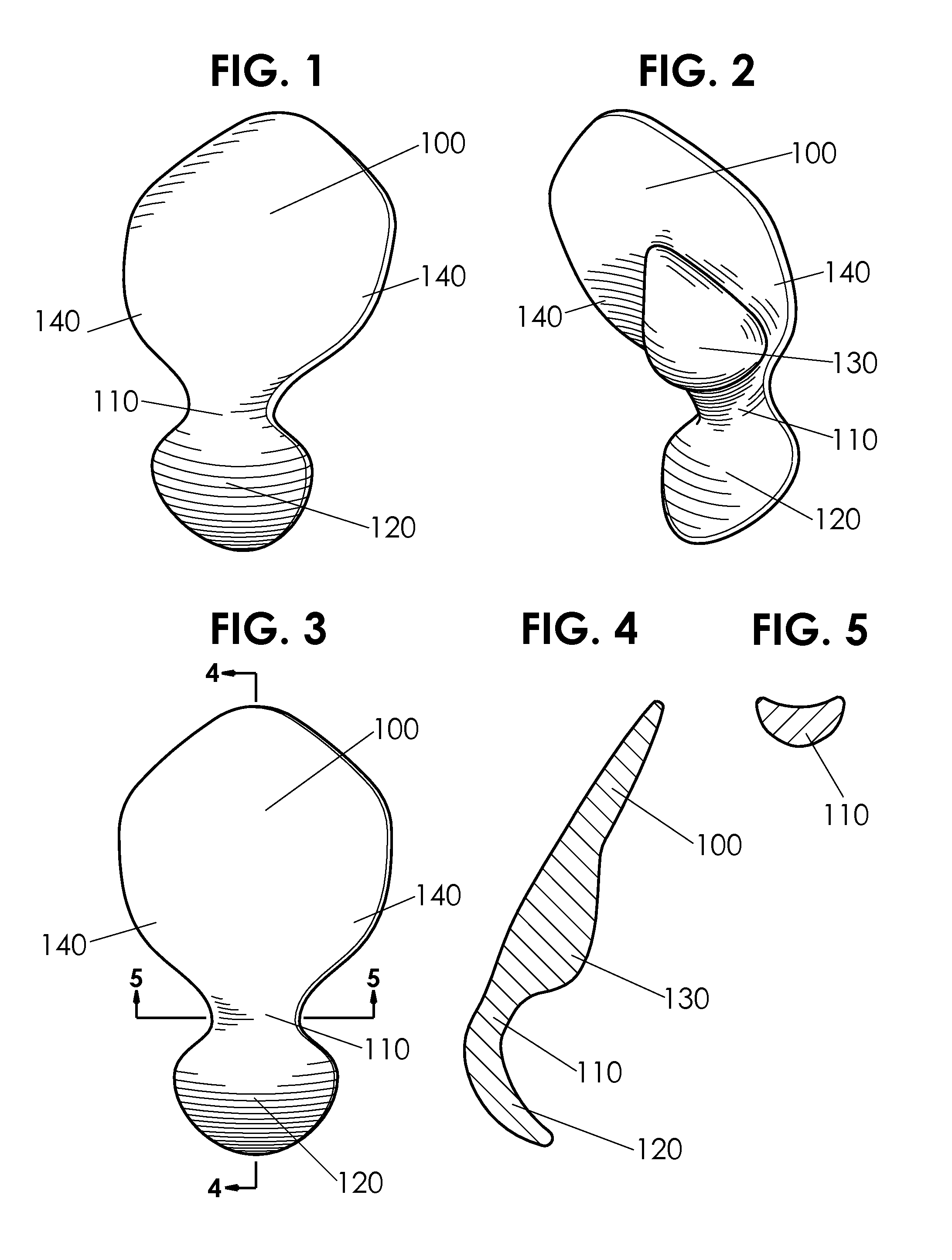
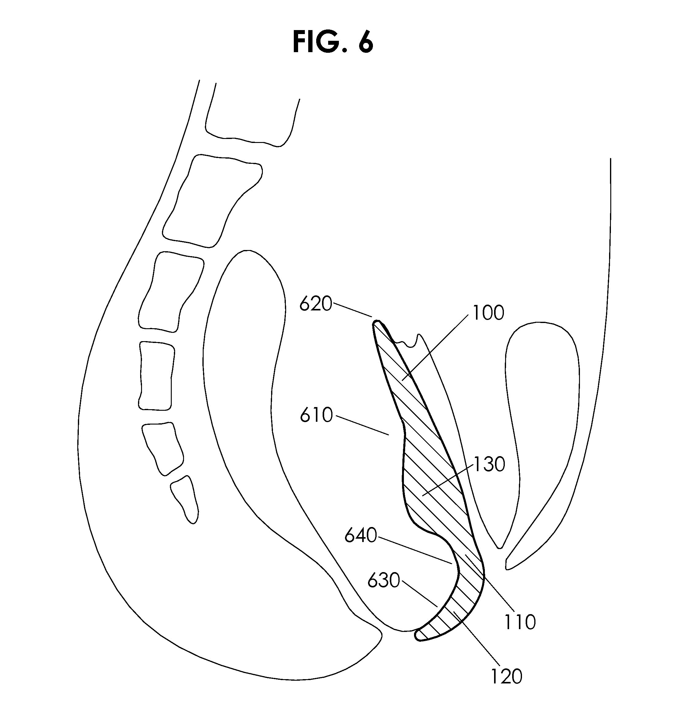
Female posterior wall prosthesis

a posterior vaginal wall and prosthesis technology, applied in the field of medical devices, can solve the problems of loss of elasticity of pain of remaining healed scar on the posterior vaginal wall, and loss of elasticity of the vaginal and vaginal entran

Active Publication Date: 2011-08-04
MAURETTE NEIL LUKE
View PDF4 Cites 7 Cited by
  • Summary
  • Abstract
  • Description
  • Claims
  • Application Information

AI Technical Summary

Problems solved by technology

After an episiotomy, vaginoplasty or vaginal tear, the remaining healed scar on the posterior vaginal wall can be painful or the area on the posterior vaginal wall can be hypersensitive.
Factors such as aging, overstretching from childbirth or sexual activities can further cause the vagina and vaginal entrance to lose elasticity.
These options have varying degrees of success and risk.
Evidence shows that noticeable tightening effects of these ointments are considered to be ineffective.
Application of the cream to the interior walls of the vagina is difficult, embarrassing, and must be properly timed to correspond with sexual intercourse.
Alum douches are not recommended by doctors, can be irritating and are associated with increased risk of pelvic and vaginal infections.
Alum is an astringent that acts to contract the vagina walls, but there is no way to judge how long the constriction will last nor a way to control the extent of tightening.
One disadvantage to these exercise methods is that it takes a long time, an average of 6 to 12 weeks, to see results, so one must be dedicated to maintain the muscle development program long enough for it to be of benefit.
In addition, like any muscle, if the muscles are not continually worked, the pubococcygeal muscles will lose their strength.
Another disadvantage is that to be of benefit during sexual intercourse, the female must consciously flex her interior muscles, thus taking away from her ability to relax and enjoy the act of intercourse itself.
Unfortunately, both of these methods are expensive and not viable for use in home conditions.
This is a costly procedure, and has the following risks: problems with anesthesia, bleeding, hematoma, infection with swelling, soreness and tenderness and post operative scarring.
There is also the risk of losing sensitivity due to complications within the vaginal wall area and muscles.

Method used


Image

  • Female posterior wall prosthesis
  • Female posterior wall prosthesis
  • Female posterior wall prosthesis

Examples


first embodiment

FIGS. 1-6—First Embodiment

[0055]One embodiment of the posterior vaginal wall prosthesis which resembles a paddle with a curved handle is illustrated in FIGS. 1-5. This embodiment comprises a flattened lobe 100, a neck 110, a handle 120, and a retention bulb 130. The flattened lobe 100 includes two side wings 140, 140. The neck 110 connects the flattened lobe 100 to the handle 120 as illustrated in FIG. 1. This embodiment comprises a flexible, resilient, unitary structure wherein the flattened lobe 100 and the handle 120 are disposed in divergent relation with an included angle in between. Within this included angle, the tear-drop shaped retention bulb 130 is positioned at the base of the flattened lobe 100 near the neck 110 with the largest part of the bulb placed closest to the neck 100 as shown in FIG. 2. The posterior vaginal wall prosthesis is sized and configured to be placed in a human female vagina as shown in FIG. 6 so that the end of the flattened lobe 100 is disposed towar...

second embodiment

FIGS. 7-11—Second Embodiment

[0061]Another embodiment of the posterior vaginal wall prosthesis is shown in FIGS. 7-11. The embodiment shown in FIGS. 7-11 comprises texture 280 on the non-bulb side, a deformable lobe retainer 240 embedded in the flattened lobe 100, a deformable handle retainer 250 embedded in the handle 120, finger holes 260 and 270, and a recess 290 in the retention bulb. Texture 280 is provided on the flattened lobe 100 on the non-bulb side and serves to act as a further means of retention by creating a higher friction surface. This surface texture 280 serves to enhance stimulation to the male sex organ and effectively duplicate the texture of the posterior vaginal wall 610. Note that localized texture 280 or texture 280 on the entire surface of the prosthesis aids to keep tampons in place. The deformable lobe retainer 240 applies continuous pressure in an attempt to flatten out the flattened lobe 100 in the vagina after insertion. The shape of the flattened lobe 10...

third embodiment

FIGS. 12-16—Third Embodiment

[0069]The embodiment of FIGS. 12-16 illustrates an embodiment of the prosthesis with a combined retainer 310. The combined retainer 310 is a unitary retainer that combines the lobe retainer 240 and the handle retainer 250 and passes through the neck 110. The combined retainer has the same purpose as the separate retainers, serving to unroll the prosthesis after being rolled up and inserted into the vagina. The combined retainer 310 also holds the flattened lobe 100 in place within the vagina and prevents the handle from entering the vagina before, during and after coitus.

[0070]The preferred material for the manufacture of this embodiment is the same material as the material described for the first embodiment shown in FIGS. 1-5. The combined retainer 310 is made of a similar and more rigid material to facilitate the added flexural function. The preferred material for the manufacture of the combined retainer 310 is that of the lobe retainer 240 material des...


PUM


Abstract

A prosthesis comprising a flattened lobe (100), a neck (110) and a handle (120) sized and shaped to shield the posterior vaginal wall from frictional contact during coitus. This self-retaining prosthesis comprises a means to retain the flattened lobe (100) within the vagina and a means to prevent the handle (120) from entering the vagina during insertion of the prosthesis or during coitus. This prosthesis decreases the volume of the vagina and decreases the area of the vaginal opening providing a non-surgical, cost-effective solution to tightening a woman's vagina. The posterior vaginal wall prosthesis enables women who have larger vaginas to use tampons.

Description

CROSS-REFERENCE TO RELATED APPLICATIONS[0001]Not ApplicableFEDERALLY SPONSORED RESEARCH[0002]Not ApplicableSEQUENCE LISTING OR PROGRAM[0003]Not ApplicableBACKGROUND[0004]1. Field[0005]This application relates generally to medical devices, particularly to a prosthesis constructed to duplicate the posterior vaginal wall.[0006]2. Prior Art[0007]After an episiotomy, vaginoplasty or vaginal tear, the remaining healed scar on the posterior vaginal wall can be painful or the area on the posterior vaginal wall can be hypersensitive. There is a need for a sensitive area covering device that can be worn on the posterior vaginal wall during coitus to reduce the friction on this area to help with the hypersensitivity in this area.[0008]In addition, a woman's vagina and vaginal entrance naturally differ in size from person to person. Factors such as aging, overstretching from childbirth or sexual activities can further cause the vagina and vaginal entrance to lose elasticity. To help tighten her...

Claims


Application Information

Patent Timeline
Patent Type & Authority Applications(United States)
IPC IPC(8): A61F6/06
CPCA61F2/005A61F2/50A61F5/41A61H19/50A61H2201/165A61F6/08
Inventor MAURETTE, NEIL LUKE
Owner MAURETTE NEIL LUKE
Why Eureka
Try Eureka