Optical disc drive

Inactive Publication Date: 2011-08-04
HITACHI-LG DATA STORAGE
View PDF10 Cites 4 Cited by
  • Summary
  • Abstract
  • Description
  • Claims
  • Application Information

AI Technical Summary

Benefits of technology

[0005]As described above, the edge of a reinforcement provided on the wiring member of a conventional optical disc drive is substantially perpendicular to the elongating direction of the wiring member. Therefore, the repulsive force against the bending of the wiring member changes when a tray is being inserted into a chassis and the reinforcement of the wiring member starts bending. The power to push the tray in inserting the tray into the chassis is to be increase against the change in the repulsive force, so that a user may feel worse in operation.
[0007]An object of this invention is to provide an optical disc drive providing improved operational feeling in inserting the tray into the chassis.
[0009]According to this invention, the optical disc drive provides a user with improved operational feeling in inserting a tray into a chassis.

Problems solved by technology

Therefore, the repulsive force against the bending of the wiring member changes when a tray is being inserted into a chassis and the reinforcement of the wiring member starts bending.
The power to push the tray in inserting the tray into the chassis is to be increase against the change in the repulsive force, so that a user may feel worse in operation.
It also happens that the tray cannot sufficiently eject because of the reinforcement.
The spring force for ejecting the tray cannot allow the reinforcement of the wiring member to start bending when the tray ejects, so that the tray may stop ejecting before the reinforcement starts bending.

Method used


Image

  • Optical disc drive
  • Optical disc drive
  • Optical disc drive

Examples


Embodiment Construction

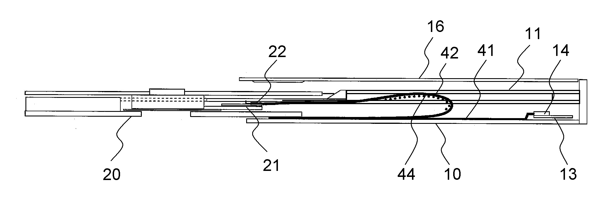
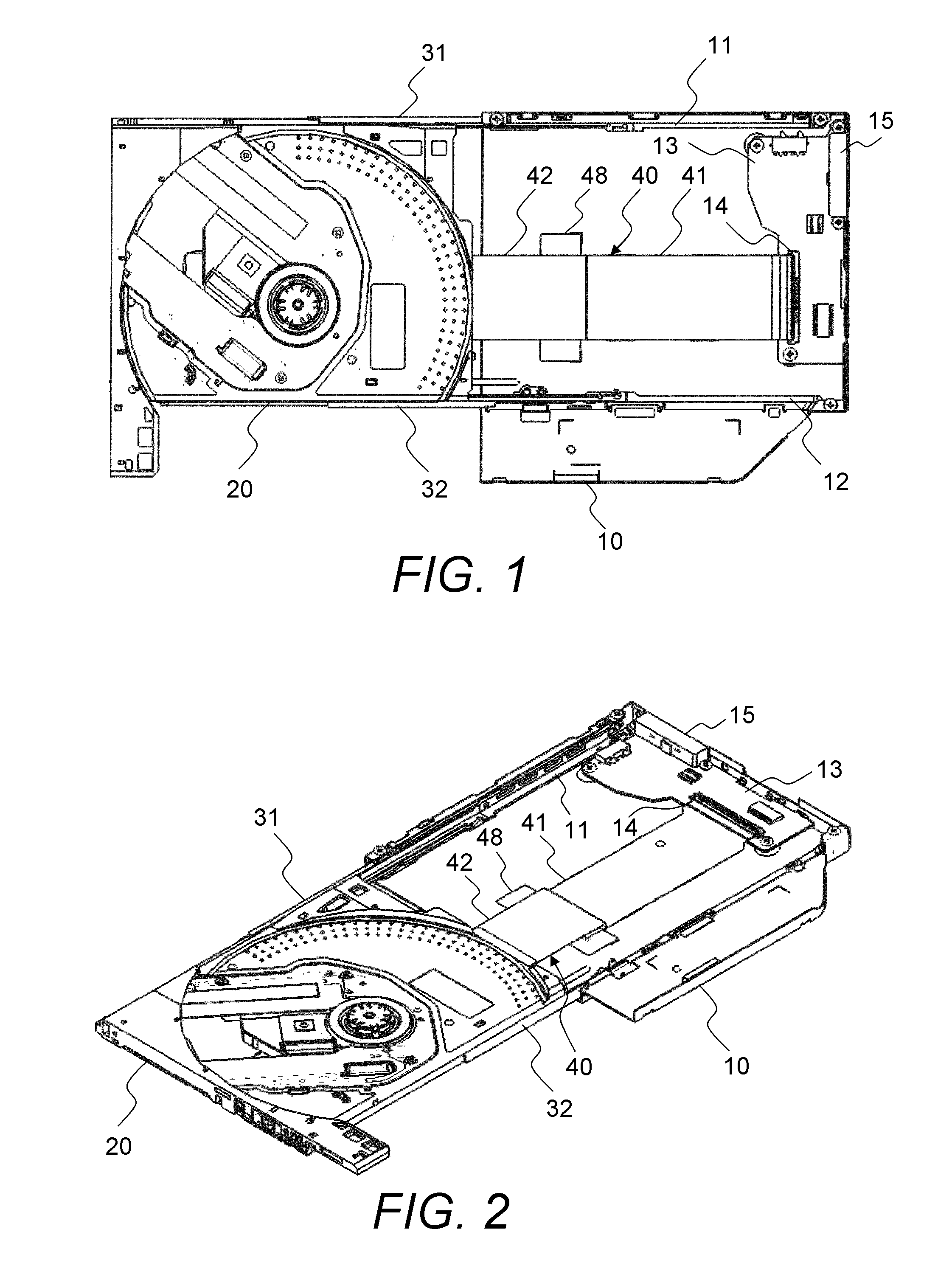
[0021]FIG. 1 is a top view of an optical disc drive in an embodiment of this invention with its top case removed and its tray opened. FIG. 2 is a perspective view thereof.

[0022]The optical disc drive in this embodiment comprises a box-shaped chassis 10 for housing a tray 20 on which an optical disc is loaded. The chassis 10 comprises a bottom wall and three side walls forming a substantially open-box shape. A top case 16 (see FIG. 5) is attached to the top of the chassis 10 to form a box-shaped chassis assembly with an opening through which the tray 20 is ejected and inserted.

[0023]The tray 20 is supported by rails 31 and 32 on its left and right sides and mounted slidably along the rails 31 and 32. On the left and right side walls of the chassis 10, sliders 11 and 12 for sliding the rails 31 and 32 are provided. The tray 20 moves from the inside of the chassis assembly to the outside of the chassis assembly with the rails 31 and 32, and the sliders 11 and 12 as it ejects from the c...


PUM


Abstract

There is provided an optical disc drive comprising: a chassis assembly formed in a box shape, including a chassis; and a tray on which an optical disc is loaded, wherein: the tray is able to move between a close state in the chassis assembly and a open state ejecting form the chassis assembly; the optical disc drive further comprises a flexible wiring member for connecting a first circuit board mounted on the chassis and a second circuit board mounted on the tray; the flexible wiring member includes a thicker reinforced part in a part of the flexible wiring member than in the other part of the flexible wiring member; and the reinforced part has a width which is narrower at an end on the chassis side than the other part of the reinforced part.

Description

CLAIM OF PRIORITY[0001]The present application claims priority from Japanese patent application JP 2010-23044 filed on Feb. 4, 2010, the content of which is hereby incorporated by reference into this application.BACKGROUND OF THE INVENTION[0002]This invention relates to an optical disc drive and, in particular, relates to a structure of a wiring member for connecting a tray and a chassis of the optical disc drive.[0003]An optical disc drive for reading and writing data from and to an optical disc such as a Blu-ray Disc (BD), has a wiring member having high flexibility such as a flexible flat cable (FFC) and a flexible printed circuit (FPC). The wiring member such as a flexible flat cable is occasionally pinched between a tray and a chassis when the tray is being inserted into a chassis of the optical disc drive, so that the wiring member is damaged.[0004]To prevent such damage of the wiring member, JP 2003-158347 A discloses a reinforcement protruding in the width of a flexible wiri...

Claims


Application Information

Patent Timeline
IPC IPC(8): G11B33/12
CPCG11B33/12H05K2201/2009H05K1/147H05K1/118G11B17/056G11B33/122
Inventor ISHIZUKA, YOSUKEKIRIHARA, SOJIROYAMAGISHI, HIROSHI
Owner HITACHI-LG DATA STORAGE
Why Eureka
Try Eureka