
Braking control system of two-wheeled motor vehicle

Active Publication Date: 2010-03-18
BOSCH CORP
View PDF10 Cites 8 Cited by
  • Summary
  • Abstract
  • Description
  • Claims
  • Application Information

AI Technical Summary

Benefits of technology

[0045]According to the invention, when a front-and-rear-wheel-interlocked brake operates, operation feeling of a brake lever is improved, and consequently more natural operation feeling may be provided to a driver.
[0046]According to the invention according to claim 7, since a first-wheel interlocked brake is separated from a first-wheel non-interlocked brake, even if the first-wheel interlocked brake operates according to front-and-rear-wheel-interlocked braking control, the first-wheel non-interlocked brake does operate, so that volume of a portion to be increased in pressure is reduced in a front-wheel hydraulic circuit. Therefore, when the first-wheel interlocked brake is increased in pressure, a response characteristic of the first-wheel interlocked brake is improved.
[0047]According to the invention according to claim 8, when a front-and-rear-wheel-interlocked brake operates, a first-wheel non-interlocked brake receives hydraulic pressure caused along with operation of a first braking operation unit. Therefore, operation feeling of the first braking operation unit is improved, and consequently more natural operation feeling may be provided to a driver.
[0048]According to the invention according to claim 9 or 10, in the case that a first-wheel interlocked brake is increased in pressure, when a first braking operation unit is operated, hydraulic pressure caused along with operation of the first braking operation unit is immediately transmitted to a first-wheel non-interlocked brake being opened while any valve is not changed in opening / closing state. Thus, operation response of the first-wheel non-interlocked brake is improved, and consequently natural operation feeling may be provided to a driver.
[0049]According to the invention according to claim 16, since a first braking operation unit is manually operated, a driver may directly feel improved operation feeling of the first braking operation unit through feeling of the driver's hand.
[0050]According to the invention according to claim 17, since a first-wheel interlocked brake is separated from a first-wheel non-interlocked brake, even if the first-wheel interlocked brake operates according to front-and-rear-wheel-interlocked braking control, the first-wheel non-interlocked brake does not operate, so that volume of a portion to be increased in pressure is reduced in a front-wheel hydraulic circuit. Therefore, when the first-wheel interlocked brake is increased in pressure, a response characteristic of the first-wheel interlocked brake is improved.

Problems solved by technology

If braking force is not appropriately balanced between the front and rear wheels, the two-wheeled motor vehicle may be fallen down.

Method used


Image

  • Braking control system of two-wheeled motor vehicle
  • Braking control system of two-wheeled motor vehicle
  • Braking control system of two-wheeled motor vehicle

Examples


first embodiment

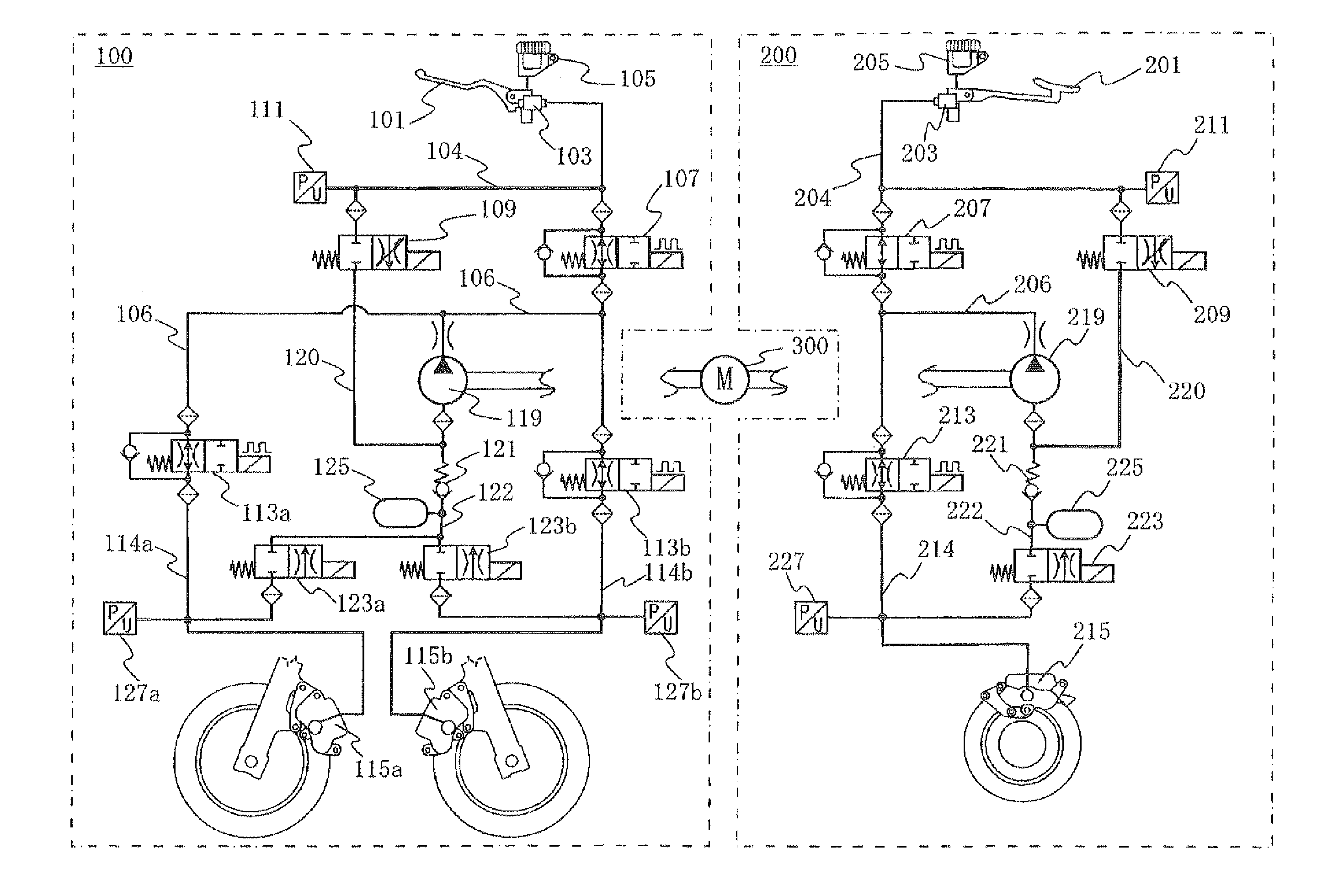
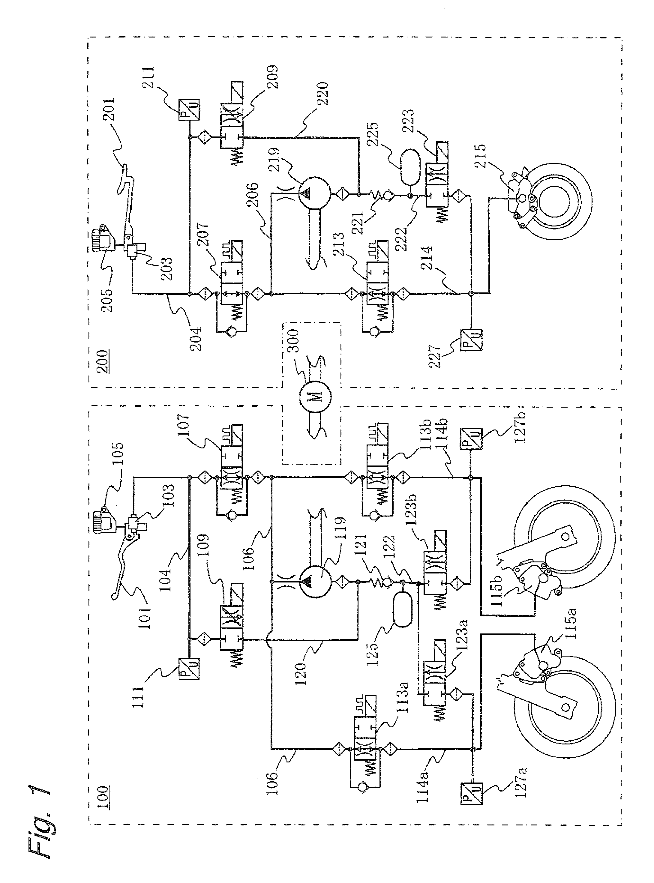
[0091]FIG. 1 shows a hydraulic circuit of a braking control system according to a first embodiment of the invention. The hydraulic circuit is configured of a front-wheel hydraulic circuit 100, a rear-wheel hydraulic circuit 200, and a DC motor 300 for driving respective hydraulic pumps in the front-wheel hydraulic circuit 100 and the rear-wheel hydraulic circuit 200.

[0092]First, a configuration of the front-wheel hydraulic circuit 100 is described. The front-wheel hydraulic circuit 100 has a brake lever 101 to be operated by a right hand of a driver, a front-wheel-side master cylinder 103 to be pressurized upon operation of the brake lever 101, a front-wheel-side master cylinder reservoir 105 connected to the front-wheel-side master cylinder 103, a front-wheel-side switching valve 107 connected to the front-wheel-side master cylinder 103 via a pipeline 104, and a front-wheel-side high-pressure intake valve 109 connected to the front-wheel-side master cylinder 103 via the pipeline 10...

second embodiment

[0119]FIG. 3 shows a hydraulic circuit of a braking control system according to a second embodiment of the invention. The hydraulic circuit is configured of a front-wheel hydraulic circuit 100, a rear-wheel hydraulic circuit 200, and a DC motor 300 for driving respective hydraulic pumps in the front-wheel hydraulic circuit 100 and the rear-wheel hydraulic circuit 200.

[0120]First, a configuration of the front-wheel hydraulic circuit 100 is described. The front-wheel hydraulic circuit 100 has a brake lever 101 to be operated by a right hand of a driver, a front-wheel-side master cylinder 103 to be pressurized upon operation of the brake lever 101, a front-wheel-side master cylinder reservoir 105 connected to the front-wheel-side master cylinder 103, a front-wheel-side switching valve 107 connected to the front-wheel-side master cylinder 103 via a pipeline 104, and a front-wheel-side intake valve 109 connected to the front-wheel-side master cylinder 103 via the pipeline 104. A filter i...

third embodiment

[0149]FIG. 5 shows a hydraulic circuit of a braking control system according to a third embodiment of the invention. The hydraulic circuit is configured of a front-wheel hydraulic circuit 100, a rear-wheel hydraulic circuit 200, and a DC motor 300 for driving respective hydraulic pumps in the front-wheel hydraulic circuit 100 and the rear-wheel hydraulic circuit 200.

[0150]First, a configuration of the front-wheel hydraulic circuit 100 is described. The front-wheel hydraulic circuit 100 has a brake lever 101 to be operated by a right hand of a driver, a front-wheel-side master cylinder 103 to be pressurized upon operation of the brake lever 101, a front-wheel-side master cylinder reservoir 105 connected to the front-wheel-side master cylinder 103, a front-wheel-side switching valve 107 connected to the front-wheel-side master cylinder 103 via a pipeline 104, and a front-wheel-side intake valve 109 connected to the front-wheel-side master cylinder 103 via the pipeline 104. A filter is...


PUM


Abstract

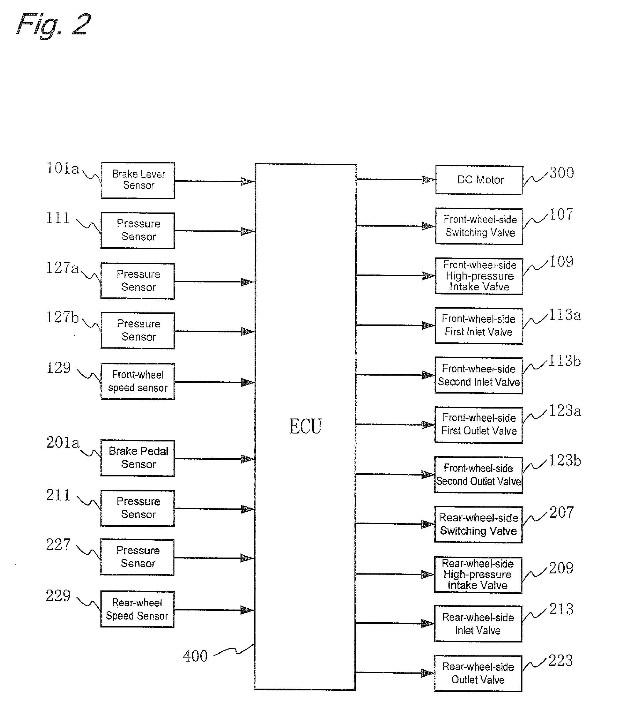
An object of the invention is to provide a braking control system of a two-wheeled motor vehicle, by which when a front-and-rear-wheel-interlocked brake operates, operation feeling of a brake lever is improved, and consequently more natural operation feeling may be provided. A braking control system of a two-wheeled motor vehicle according to the invention performs front-and-rear-wheel-interlocked braking control that allows a front-wheel brake and a rear-wheel brake to operate in an interlocked manner. The front-wheel brake is configured of a front-wheel first brake and a front-wheel second brake. ECU 400 controls a front-wheel hydraulic circuit 100 so that the first brake operates according to the front-and-rear-wheel-interlocked braking control. Furthermore, the ECU 400 controls the front-wheel hydraulic circuit 100 so that the front-wheel second brake receives hydraulic pressure caused along with operation of a brake lever 101 during performing the front-and-rear-wheel-interlocked braking control. Thus, operation feeling of the brake lever 101 is improved.

Description

TECHNICAL FIELD[0001]The present invention relates to a braking control system of a two-wheeled motor vehicle, and more particularly, relates to a braking control system of a two-wheeled motor vehicle, in which operation feeling of a brake lever is improved.BACKGROUND ART[0002]In a two-wheeled motor vehicle, a front-wheel brake is operated by a right brake lever, and a rear-wheel brake is operated by a right brake pedal. If braking force is not appropriately balanced between the front and rear wheels, the two-wheeled motor vehicle may be fallen down. Thus, a driver needs to operate the right brake lever and the right brake pedal so as to appropriately keep balance of braking force between the front and rear wheels. Furthermore, for example, patent documents 1, 2 and 3 propose front-and-rear-wheel-interlocked braking systems respectively, in which balance of braking force between the front and rear wheels is appropriately controlled regardless of how a driver operates the lever and t...

Claims


Application Information

Patent Timeline
IPC IPC(8): B60T8/171B62L3/08
CPCB60T8/1706B60T8/261B62L3/08B60T8/4072B60T8/3225
Inventor ATSUSHI, HIROAKIMASUNO, TOHRU
Owner BOSCH CORP
Learn More