
Shift device

a technology of a shift lever and a switch, which is applied in the direction of gearing control, mechanical equipment, transportation and packaging, etc., can solve the problems of poor deterioration of the operability of the shift lever, and difficulty for the driver to see the shift lever

Inactive Publication Date: 2013-03-05
HONDA MOTOR CO LTD
View PDF21 Cites 1 Cited by
  • Summary
  • Abstract
  • Description
  • Claims
  • Application Information

AI Technical Summary

Benefits of technology

The shift device described in this patent improves the visibility and operability of the shift lever for drivers. The shift lever is positioned in the meter visor above the center axis of the steering wheel, allowing for smooth shifting and operation. The device is also designed to enhance the natural operation feeling for drivers. Overall, this shift device provides better visibility, operability, and a natural operation experience for drivers.

Problems solved by technology

However, the shift devices disclosed in Japanese Patent No. 2933965 and Japanese Unexamined Patent Application Publication No. 05-246260 have a problem that it is difficult for a driver to see a shift lever since the shift lever is hidden by the steering wheel.
These shift devices also have a problem that their operability is not good since the shift lever is arranged in the operating range of a wiper control lever from the viewpoint of the driver.
The shift device disclosed in Japanese Unexamined Patent Application Publication No. 05-246260 also has a problem that its operability is deteriorated because the shift device is provided on the same height level as the steering wheel shaft or below the height level of the steering wheel shaft (similarly to a general shift device arranged on an instrumental panel) and the shift device is arranged away from the steering wheel.
If the shift lever is not arranged in the area upper than the center axis of the steering wheel but is arranged to the side of the center shaft of the steering wheel, the shift lever is positioned away from the steering wheel, which deteriorates the operability of the shift lever.
If the shift device is arranged lower than the center axis of the steering wheel, the shift device needs to be arranged in a position other than the driving sheet, which makes the shift lever away from the steering wheel, deteriorating the operability of the shift lever.

Method used


Image

  • Shift device
  • Shift device
  • Shift device

Examples


Embodiment Construction

[0052]An embodiment of the present invention is described with reference to the accompanying drawings.

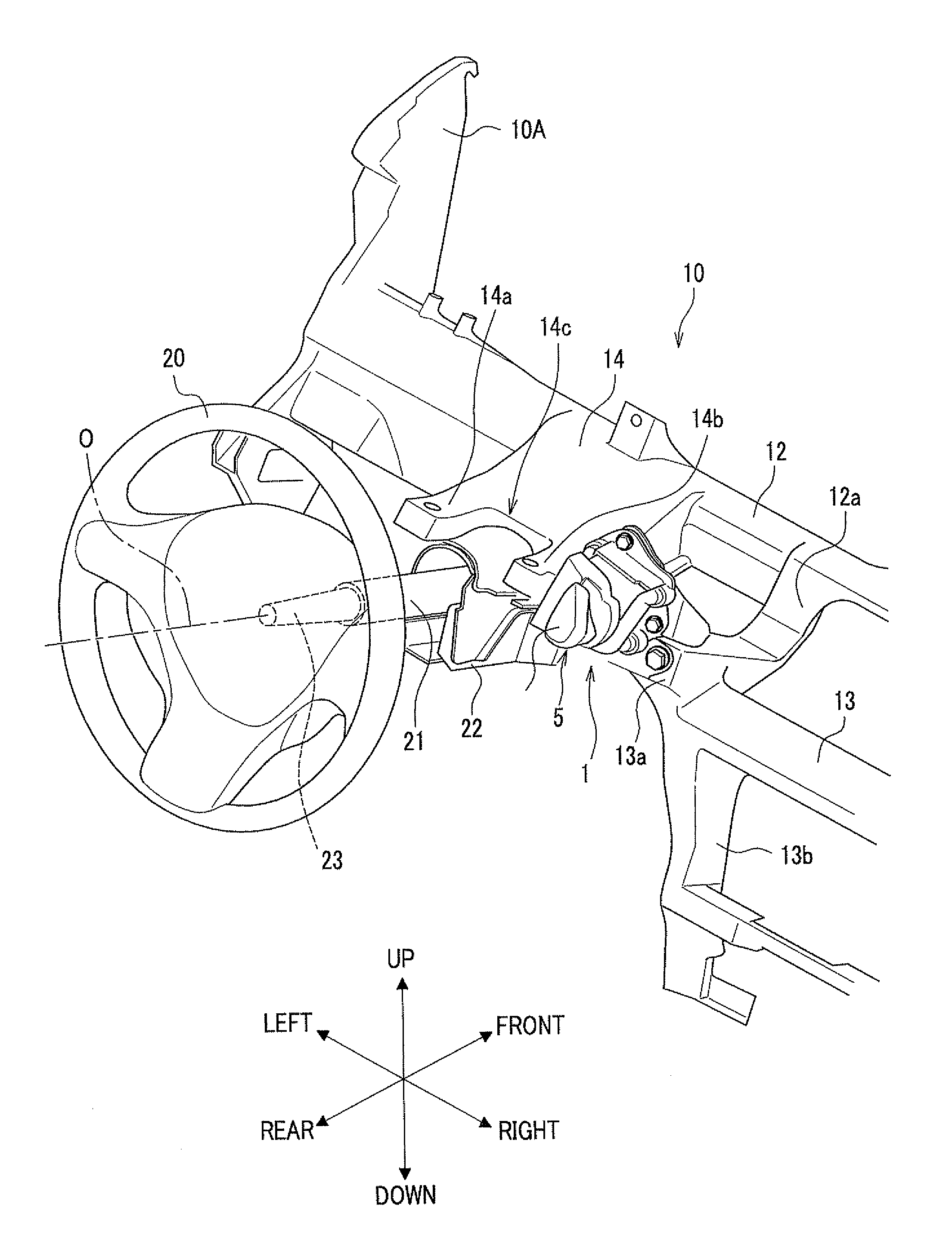
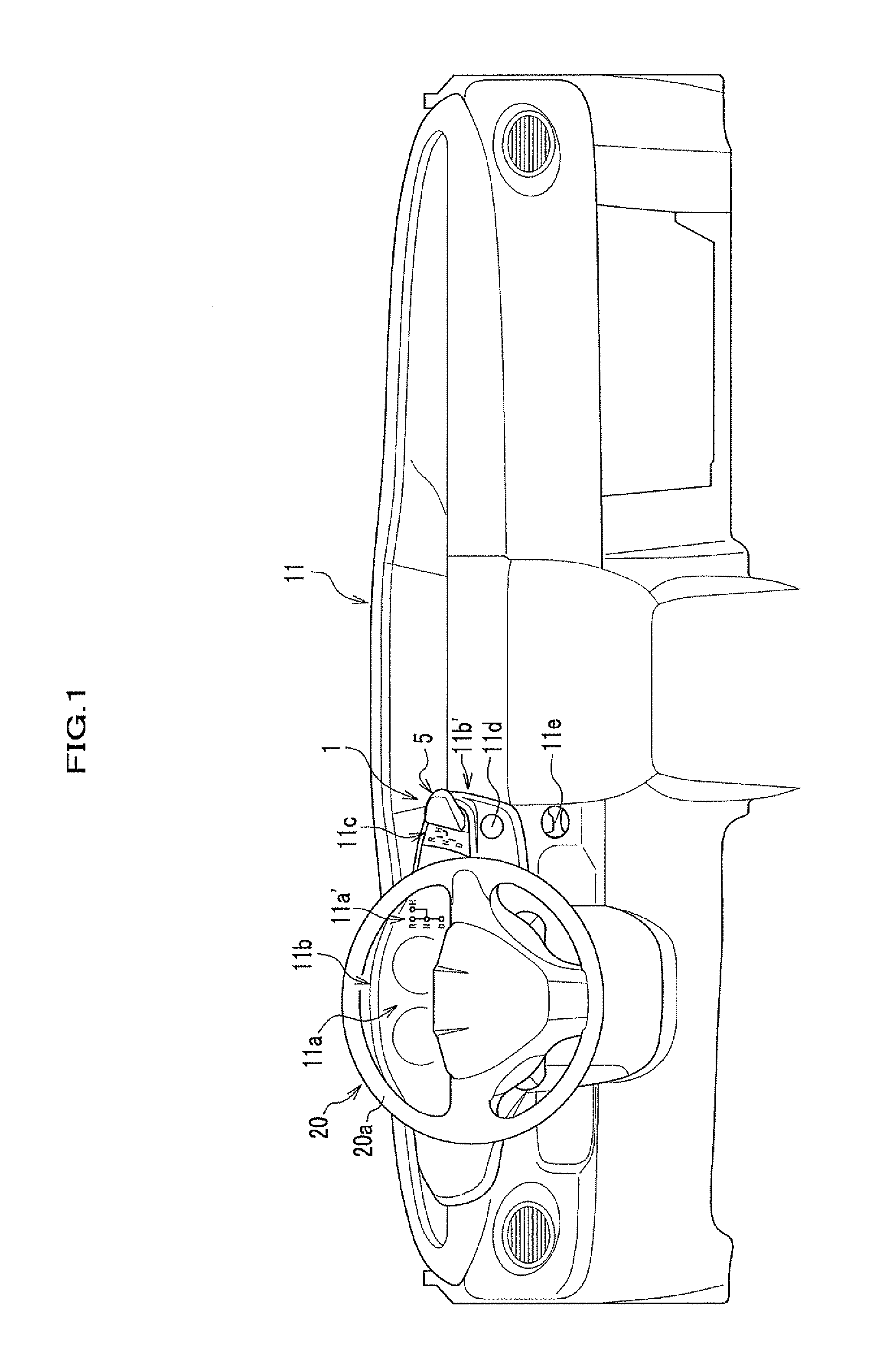
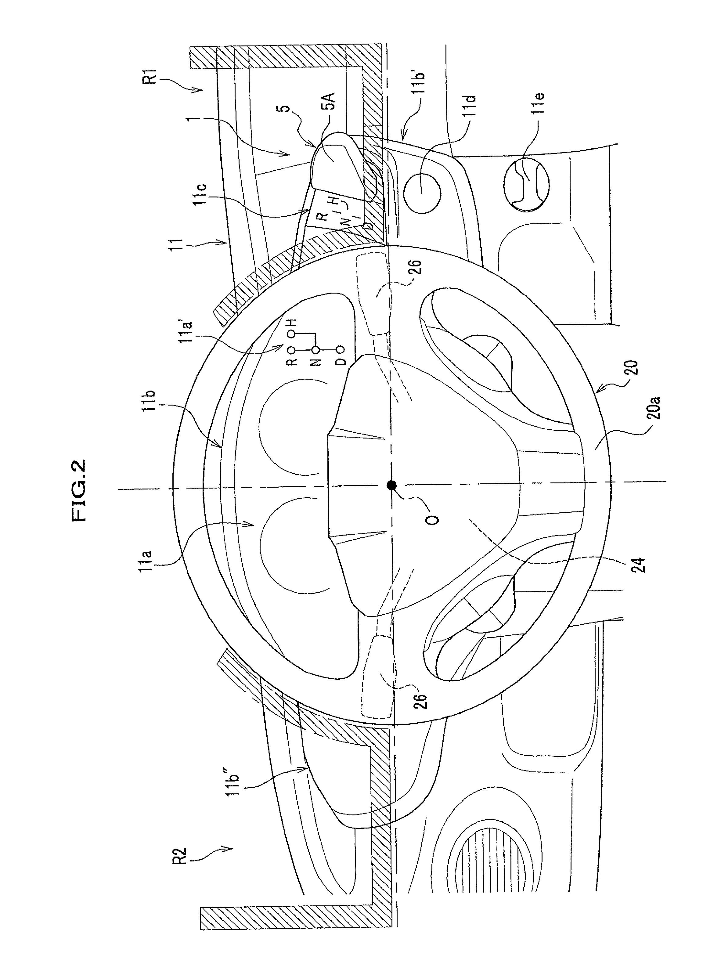
[0053]FIG. 1 is a view showing substantially entire configuration of an instrumental panel on which a shift device of the embodiment of the present invention is arranged. FIG. 2 is a view showing a position on which the shift device is arranged. FIG. 3 is a perspective view showing a mounting state of the shift device on a steering hanger beam. Hereinafter, directions of “front-back”, “right-left”, and “up-down” in this specification are the same as those of the shift device which is mounted on a vehicle body. Incidentally, a shift device 1 mounted on a vehicle body of an automobile is described hereinafter, however, the type of a vehicle with which the shift device 1 is provided is not limited to an automobile.

[0054]As shown in FIG. 1, the shift device 1 is arranged on a right end portion 11b′ of a meter visor 11b of an instrumental panel 11 which is provided in front of front shee...


PUM


Abstract

There is provided a shift device of which visibility and operability is excellent. The shift device 1 includes a shift lever 5 which operates a gear position of a transmission. The shift lever is arranged in an area R1 of an instrumental panel 11 which is outside of a steering wheel 20 and upper than the center axis O of the steering wheel 20 from the viewpoint of the driver and protruding toward the driver. A center part of the steering wheel 20 is provided with an air bag system, and the shift lever 5 is arranged in an expansion area of an air bag of the air bag system from the viewpoint of the driver.

Description

BACKGROUND OF THE INVENTION[0001]1. Field of the Invention[0002]The present invention relates to a shift device for switching a running range of an automatic transmission provided in a vehicle such as an automobile.[0003]2. Description of the Related Art[0004]Conventionally, a shift device is generally arranged on a center console which is provided between the right and left front sheets, however, there has been recently proposed a shift device which is arranged in the vicinity of a steering wheel for enlarging a space in a vehicle cabin to enhance its layout capability.[0005]For example, Japanese Patent No. 2933965 discloses a shift device which is provided on a side of a steering column. Japanese Unexamined Patent Application Publication No. 05-246260 discloses a shift device provided in a part of an instrumental panel.[0006]However, the shift devices disclosed in Japanese Patent No. 2933965 and Japanese Unexamined Patent Application Publication No. 05-246260 have a problem that i...

Claims


Application Information

Patent Timeline
Patent Type & Authority Patents(United States)
IPC IPC(8): B60K20/08
CPCB60K20/06F16H59/0204Y10T74/2014Y10T74/20146F16H59/0278
Inventor ISHIHARA, YOKOKOMATSU, ATSUSHINISHIKAWA, YOSHIKAZUOKUHARA, TATSUYANAKAMURA, TAKAHIRO
Owner HONDA MOTOR CO LTD
Learn More