

Roman shade lift system
- Summary
- Abstract
- Description
- Claims
- Application Information
AI Technical Summary
Benefits of technology
Problems solved by technology
Method used
Image

Examples
Embodiment Construction
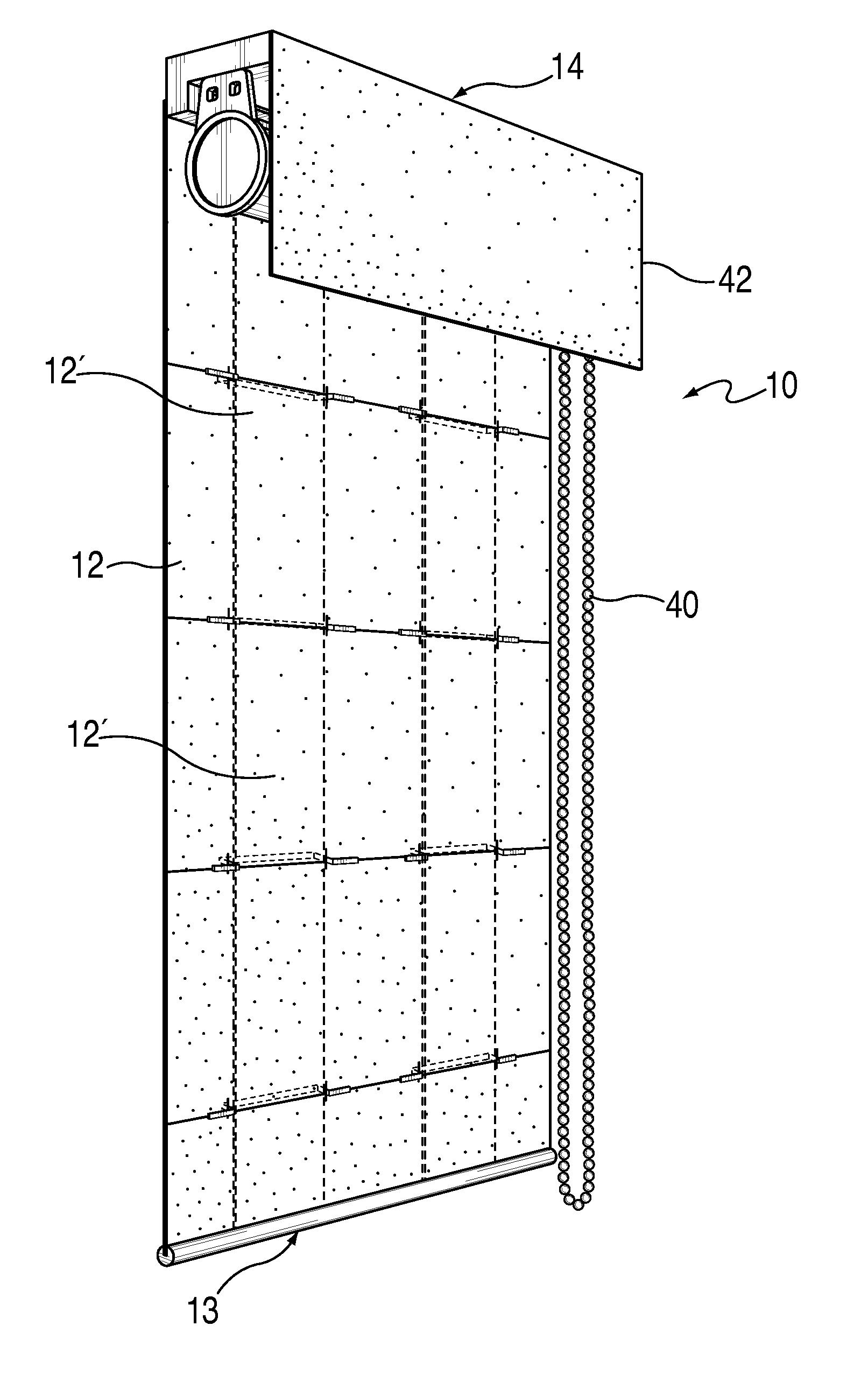
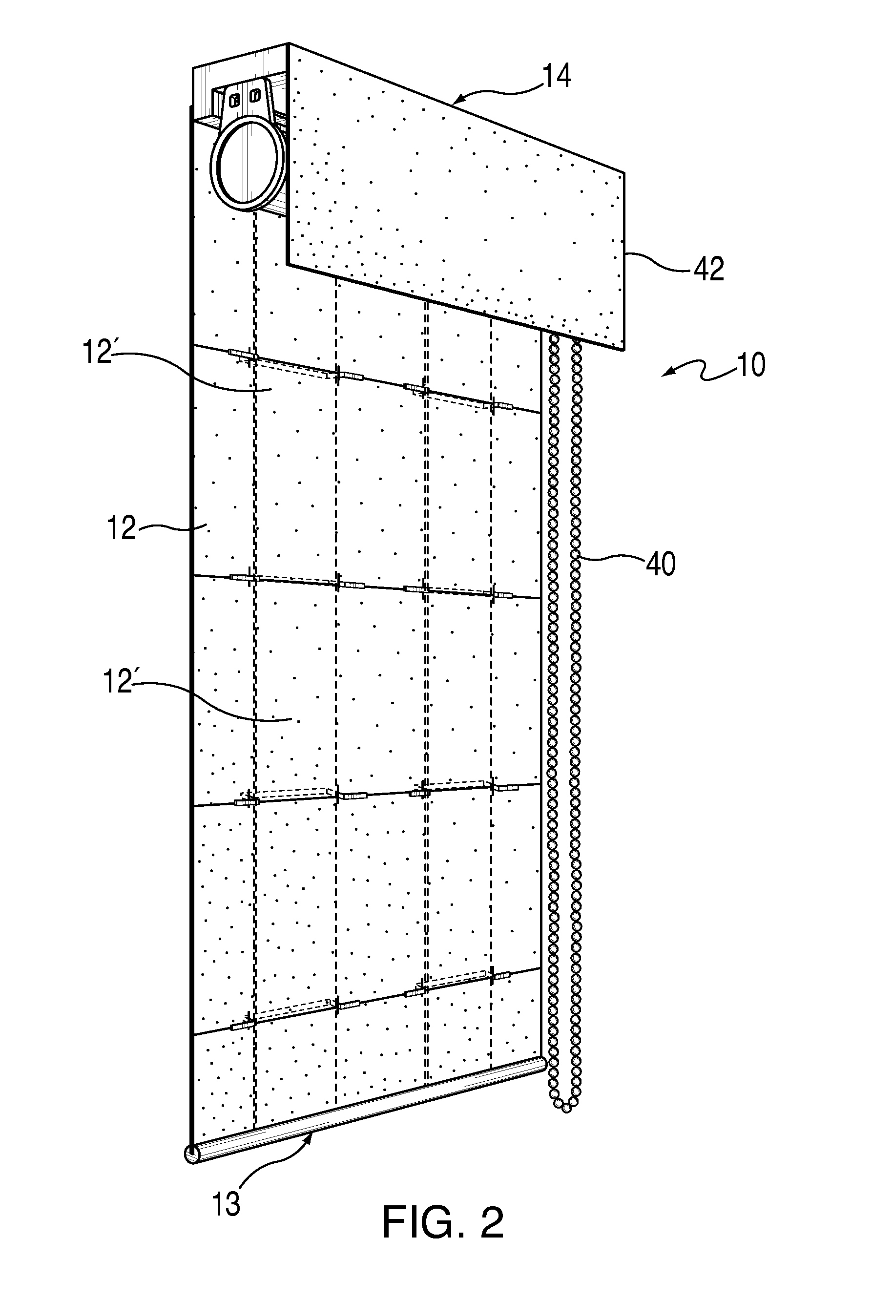
[0019]The term “roman shade” as used herein refers to a window treatment consisting of a flat panel made of a woven or non-woven fabric, or other material such as woven wood, plastic, etc., which is selectively lifted by a user (either by manual or motorized means) in a manner that causes horizontal sections of the panel to generate successive folds or pleats.
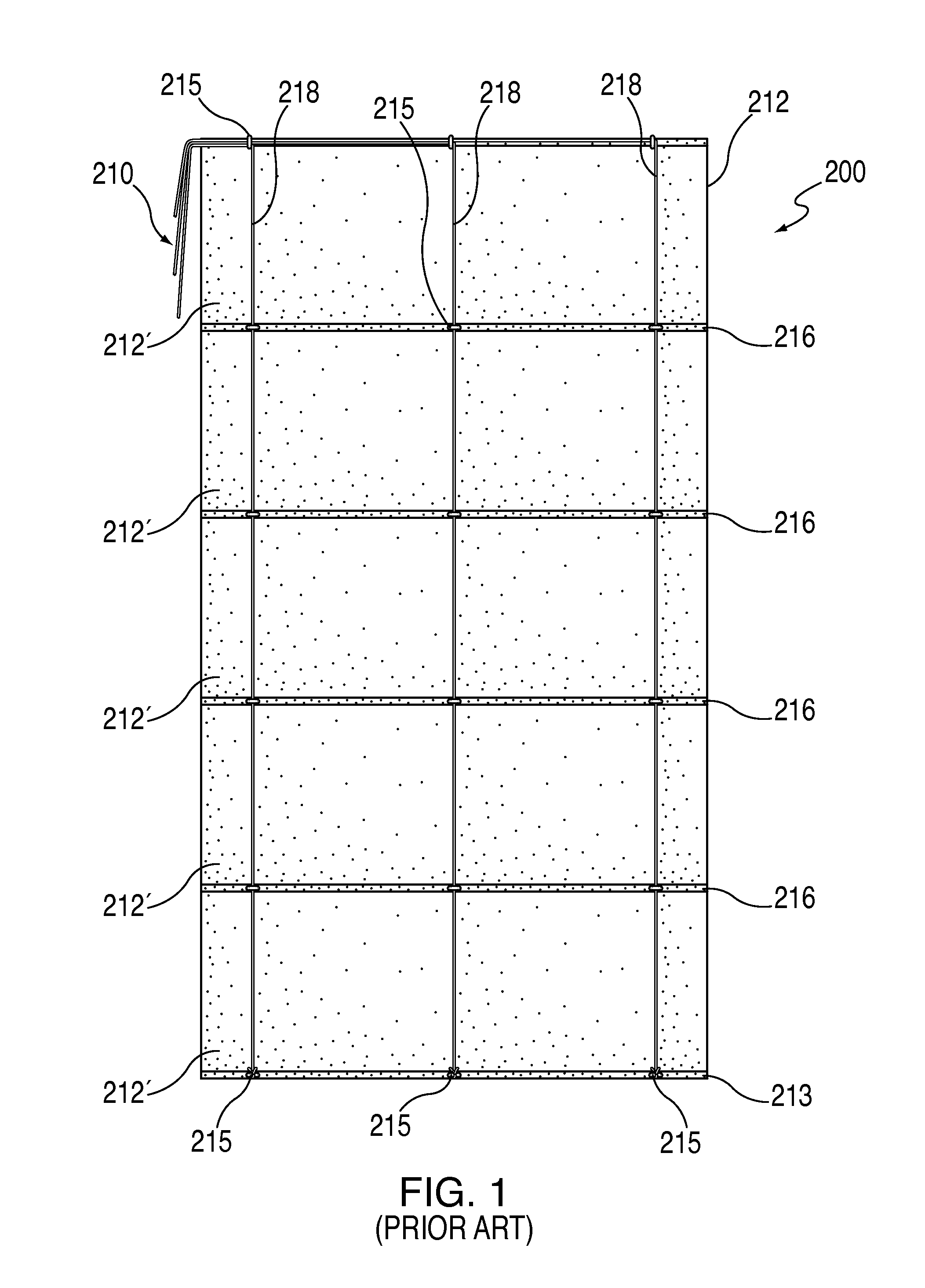
[0020]A typical prior art roman shade 200 is shown somewhat diagrammatically in FIG. 1 and it consists of a panel 212 made of a fabric or other decorative material that is relatively supple, as describe above. At the bottom of the panel 212, there is provided a hembar 213 or other elongated member extending along the width of the panel 212 to maintain the panel 212 in a stretched and relatively planar configuration when opened, and to also assist in the operation of the shade. A headrail (not shown) is provided on the top for supporting the panel 212 after mounting.
[0021]As is conventional with such window coverings, the panel ...
PUM
 Abstract
Description
Claims
Application Information