Magnetocaloric thermal generator

Inactive Publication Date: 2011-08-11
COOLTECH APPL S
View PDF22 Cites 10 Cited by
  • Summary
  • Abstract
  • Description
  • Claims
  • Application Information

AI Technical Summary

Benefits of technology

[0010]The present invention aims to overcome these disadvantages by proposing a magnetocaloric heat generator that is easy to implement

Problems solved by technology

Its limits in terms of its useful calorific output and its efficiency are also well known.
This thermal module M has a disadvantage linked with the fact that, to reach a temperature gradient, a heat transfer fluid must be circulated through the whole of the materials.
But the increase of the speed leads to an increase of the pres

Method used


Image

  • Magnetocaloric thermal generator
  • Magnetocaloric thermal generator
  • Magnetocaloric thermal generator

Examples


Embodiment Construction

[0032]In the implementation examples shown, the identical parts or sections have the same numerical references.

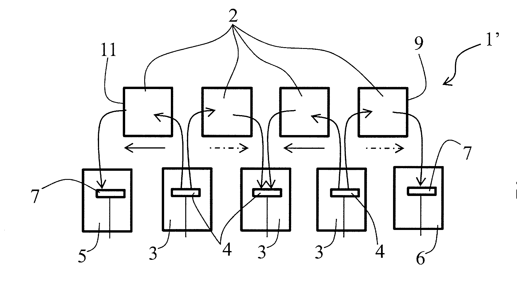
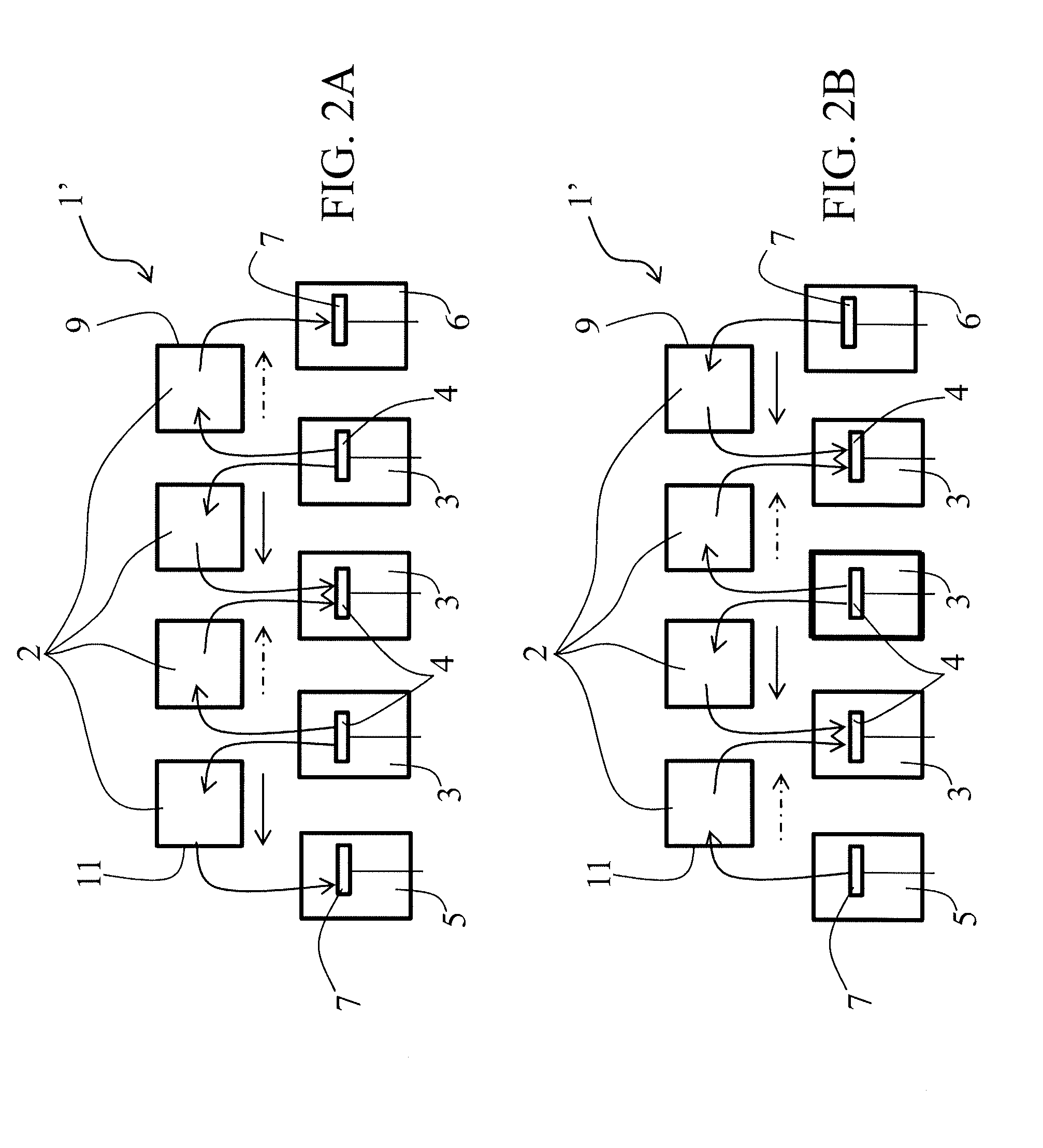
[0033]The heat generator 1 represented in FIGS. 3 and 4 is carried out according to a first embodiment of the invention. It includes two thermal modules 1′ each comprising aligned magnetocaloric elements 2. A common chamber 3 comprising a piston 4, that makes up a forced circulation means of the heat transfer fluid, is placed every time between two adjacent magnetocaloric elements 2. Furthermore, the heat module 1′ also comprises two end chambers 5 and 6 located at the hot end 9 and cold end 11 of the thermal module 1′, each also comprising a piston 7 making up a circulation means.

[0034]Each magnetocaloric element 2 can be crossed by a heat transfer fluid that is circulated by the pistons 4, 7 and is subjected to a magnetic field variation by means of a (not represented) magnetic arrangement which generates alternating heating and cooling cycles. The displacement of the pis...


PUM


Abstract

A heat generator (1) comprises at least one thermal module (1′) which contains at least two adjacent magnetocaloric elements (2), and a common distribution chamber (3), associated with a heat transfer fluid circulation device (4), fluidly connects the adjacent magnetocaloric elements (2) with one another. Two end chambers (5, 6) are associated with a circulation means (7) and fluidly connected each with the two magnetocaloric elements (2) located at the hot end (9) and a cold (11) end of the thermal module (1). A magnetic arrangement of the heat generator (1) subjects each of the magnetocaloric element (2) to a variable magnetic field. The circulation mechanism (4), associated with the common distribution chamber (3), moves the heat transfer fluid simultaneously through the two adjacent magnetocaloric elements (2) in different circulation directions.

Description

[0001]This application is a National Stage completion of PCT / FR2009 / 001223 filed Oct. 20, 2009, which claims priority from French patent application Ser. No. 08 / 05901 filed Oct. 24, 2008.FIELD OF THE INVENTION[0002]The present invention relates to a heat generator comprising at least one thermal module containing at least two adjacent magnetocaloric elements arranged for being crossed by a heat transfer fluid, a common distribution chamber associated with a heat transfer fluid circulation means which fluidly connects adjacent magnetocaloric elements with each other and two end chambers also associated with a circulation means and respectively fluidly connected with the magnetocaloric element located at the ends of the thermal module, called the hot end and the cold end, and a magnetic arrangement which subjects each magnetocaloric element to a variable magnetic field, creating alternately in each magnetocaloric element a heating cycle and a cooling cycle, circulation of the heat tra...

Claims


Application Information

Patent Timeline
IPC IPC(8): H05B6/02
CPCF25B21/00Y02B30/66H01L37/04F25B2321/002Y02B30/00H10N15/20F25B29/00
Inventor MULLER, CHRISTIANHEITZLER, JEAN-CLAUDE
Owner COOLTECH APPL S
Why Eureka
Try Eureka