Thermal generator with magnetocaloric material

a generator and magnetocaloric material technology, applied in the field of heat generators, can solve the problems of premature degradation of generator efficiency, disadvantage inherent in driving these pistons, and well-known limitations in terms of useful calorific output and efficiency, and achieve the effects of preserving efficiency, and reducing the number of constitutive components

Inactive Publication Date: 2011-08-11
COOLTECH APPL S
View PDF13 Cites 72 Cited by
  • Summary
  • Abstract
  • Description
  • Claims
  • Application Information

AI Technical Summary

Benefits of technology

[0006]The present invention aims to overcome these disadvantages by proposing a magnetocaloric generator of a simple construction having a reduced number of constitutive components, in which, on the one hand, the risk of sealing loss between the chamber in which these means of fluid circulation move and the means of driving them are greatly limited and on the other hand, whose service life is increased and efficiency is preserved.
[0008]The heat generator thus comprises a single device for driving the means of displacing the heat transfer fluid. The use of the switching interface allows avoiding the use of switching valves or other similar devices and thus facilitates the design of the heat generator. Besides, the integration of this interface in the heat generator, according to the invention, enables reducing the dimensions of the generator.
[0015]In a first variant, the magnetic arrangement may be concentric to the central axis and driven in rotation around the axis, and the switching plates and the magnetic arrangement may be rotationally driven around the central axis by the same actuator. This configuration allows making the heat generator more compact.
[0018]By integrating identical switching plates, the manufacturing cost of the generator can be reduced.

Problems solved by technology

Its limits in terms of useful calorific output and efficiency are also well known.
This generator however presents a disadvantage that is inherent to driving these pistons.
In fact, this drive is subjected to the wear of the components in contact, that is, the cam profile and the pistons, which can result in a premature degradation of the generator efficiency.
Moreover, it poses problems of sealing between the piston sleeves and the drive mechanism.

Method used


Image

  • Thermal generator with magnetocaloric material
  • Thermal generator with magnetocaloric material
  • Thermal generator with magnetocaloric material

Examples


Embodiment Construction

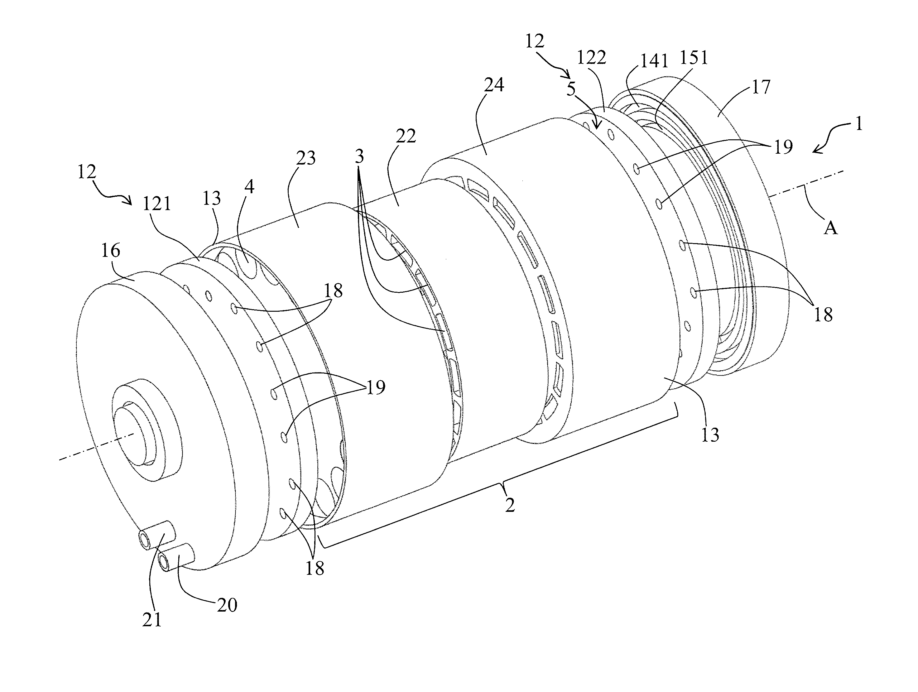
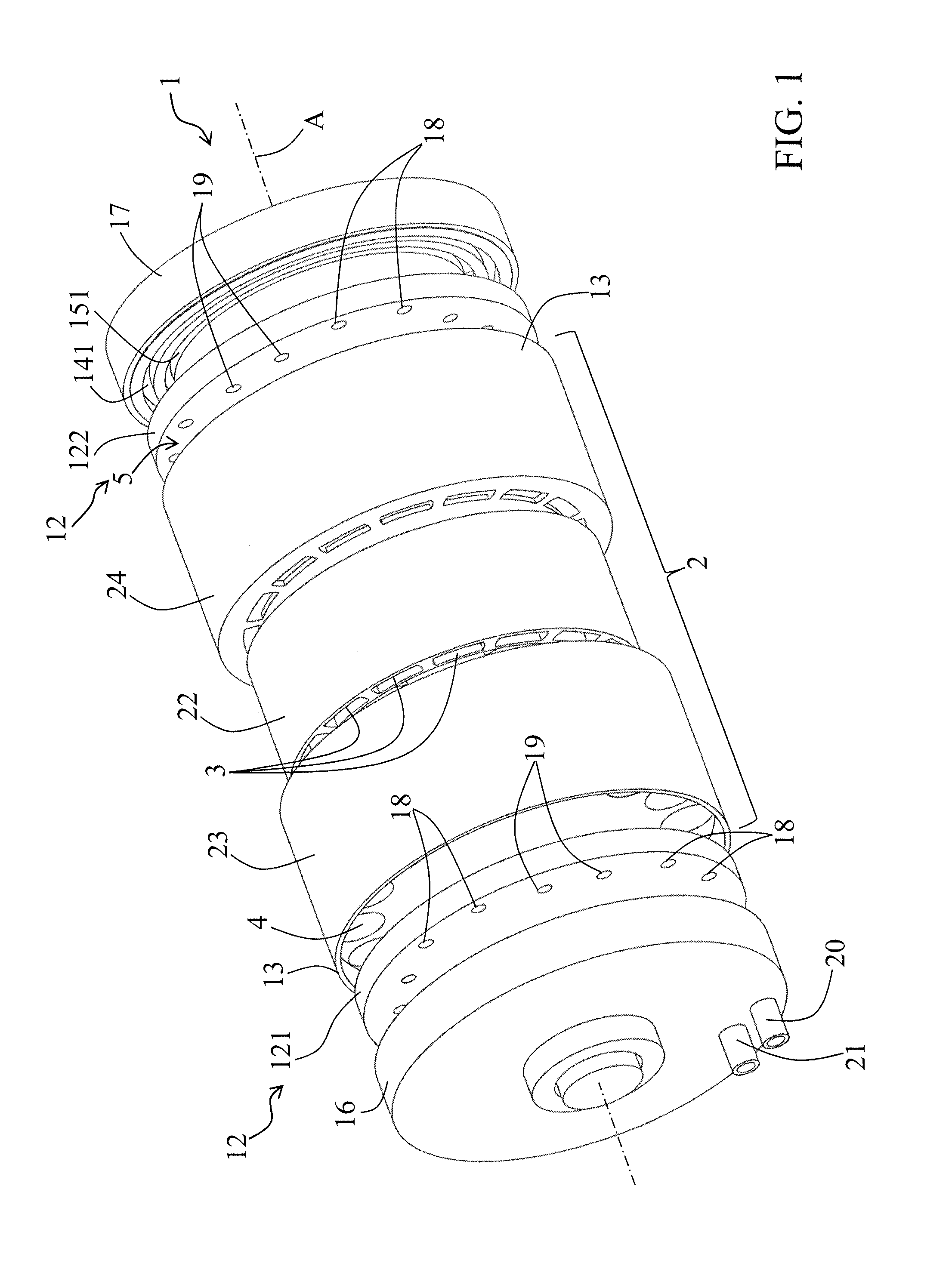
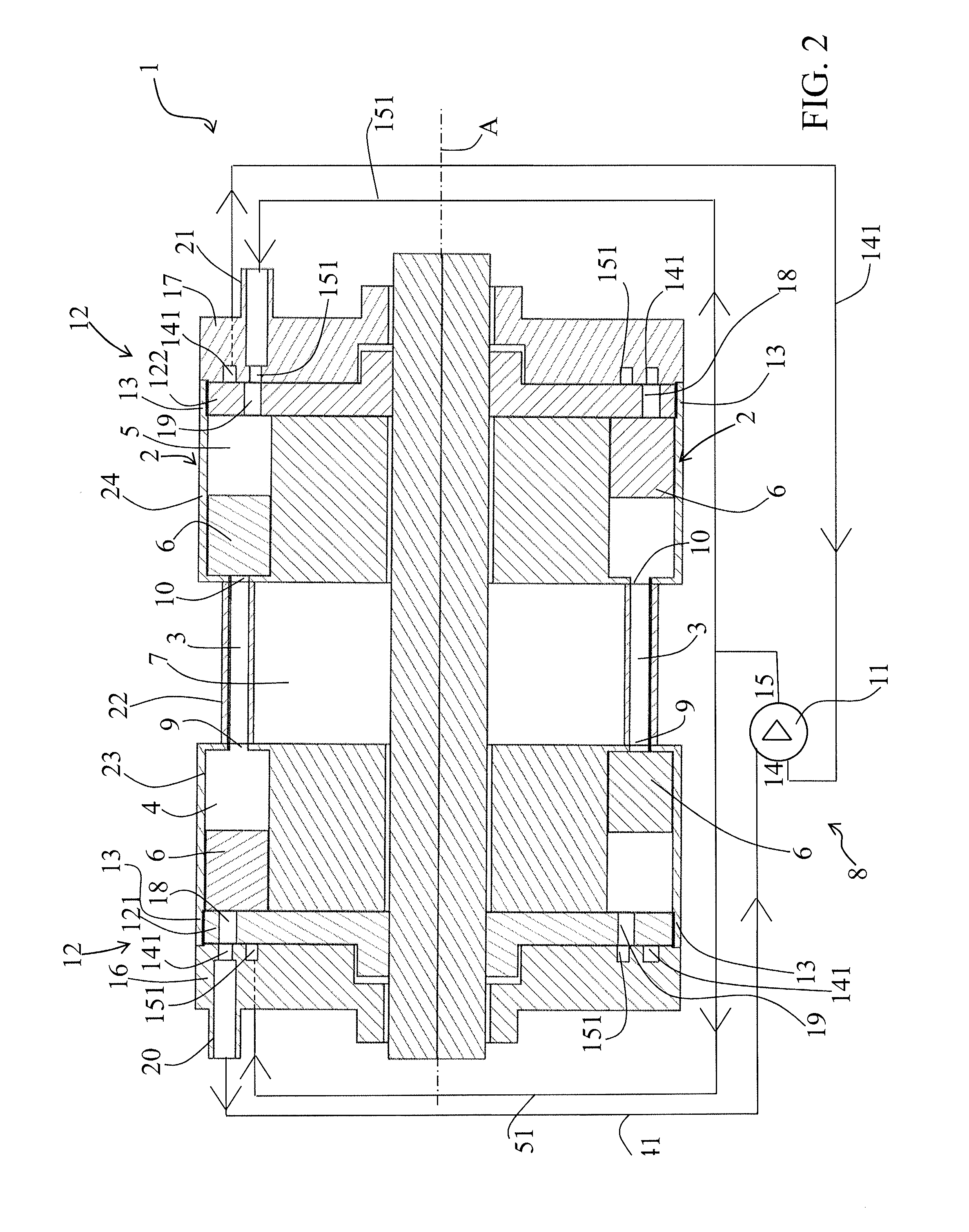
[0027]With reference to the enclosed figures, the heat generator 1 is of an approximately circular configuration. It comprises several thermal modules 2 arranged in a circle around an axis A and each containing a magnetocaloric element 3 arranged between the two hot 4 and cold 5 chambers and two means 6 for displacing a heat transfer fluid through the magnetocaloric element 3. These means of displacement are in the form of pistons 6 (see FIG. 2) arranged in the hot 4 and cold 5 chambers, between the bottom of these chambers and the hot end 9 or cold end 10 of the magnetocaloric element 3.

[0028]The bottom of the hot 4 or cold 5 chambers means the end of the chamber opposite the magnetocaloric element 3.

[0029]The magnetocaloric element 3 allows for the flow of the heat transfer fluid and it may be made up of one or more magnetocaloric materials. It has open fluid passages that may be formed of the pores of porous material, mini or micro-channels machined in a solid block or obtained b...


PUM


Abstract

A heat generator comprising at least one thermal module comprising a magnetocaloric element crossed by a heat transfer fluid and two hot and cold chambers arranged on each side of the magnetocaloric element and containing a displacement device for directing the heat transfer fluid through the magnetocaloric element. A magnetic arrangement creates a magnetic field variation in each magnetocaloric element. A device for driving the displacement device, according to reciprocating movement in the concerned chamber, to displace the heat transfer fluid in synchronization with the magnetic field variation. The drive device contains a closed fluid circuit which connects the hot and cold chambers in which a working fluid is driven by a suction and discharge device. At least one switching interface is synchronized with the magnetic arrangement for alternately connecting each hot and cold chamber to suction and discharge sides of the suction and discharge device and inversely.

Description

[0001]This application is a National Stage completion of PCT / FR2009 / 001199 filed Oct. 13, 2009, which claims priority from French patent application Ser. No. 08 / 05666 filed Oct. 14, 2008.FIELD OF THE INVENTION[0002]The present invention relates to a heat generator comprising at least one thermal module composed essentially of a magnetocaloric element arranged for being crossed by a heat transfer fluid and two hot and cold chambers arranged on each side of the magnetocaloric element and each containing a means for displacing the heat transfer fluid through the magnetocaloric element, a magnetic arrangement arranged for creating a magnetic field variation in the magnetocaloric element so as to alternately create in the magnetocaloric element a heating cycle and a cooling cycle, and a device for driving the displacement means according to a reciprocating movement in the concerned chamber for displacing the heat transfer fluid on either end of the magnetocaloric element in synchronizati...

Claims


Application Information

Patent Timeline
Patent Type & Authority Applications(United States)
IPC IPC(8): H05B6/10
CPCF25B21/00Y02B30/66H01L37/04F25B2321/0022Y02B30/00H10N15/20
Inventor MULLER, CHRISTIANHEITZLER, JEAN-CLAUDE
Owner COOLTECH APPL S
Why Eureka
Try Eureka