Movable contactor assembly for current limiting type molded case circuit breaker

a contactor assembly and current limit technology, applied in circuit breakers, circuit breakers for excess currents, snap-action arrangements, etc., can solve the problems of loss increased fabrication costs, and long time taken to fabricate spring support pins, so as to improve assembly productivity, improve the efficiency of electric power transmission, and reduce the number of components

Active Publication Date: 2011-08-11
LS IND SYETEMS CO LTD
View PDF5 Cites 14 Cited by
  • Summary
  • Abstract
  • Description
  • Claims
  • Application Information

AI Technical Summary

Benefits of technology

[0024]An aspect of the present invention provides a movable contactor assembly for a current limiting type MCCB capable of improving the efficiency of electric power transmission between a movable contactor and a terminal base, improving assembling productivity by reducing the number of components, and quickly providing a spring support mechanism at a low cost through pressing.

Problems solved by technology

However, the movable contact assembly for the current limiting type MCCB as described above has a structure in which the extending portions 18a, which have a poor flexibility, are pushed to be brought into contact with the rear end portions 11b of the movable contactors 11 by the Belleville washer or the wave washer, and in this case, because the contact area between the extending portions 18a of the terminal base 18 and the rear end portions 11b of the movable contactors 11 is narrow and has a high contact resistance, making a loss of electric power transmission.
Thus, much time is taken to fabricate the spring support pins 15 and the fabrication cost is increased.

Method used


Image

  • Movable contactor assembly for current limiting type molded case circuit breaker
  • Movable contactor assembly for current limiting type molded case circuit breaker
  • Movable contactor assembly for current limiting type molded case circuit breaker

Examples


Embodiment Construction

[0052]The configuration and operation of a movable contactor assembly for a current limiting type molded case circuit breaker (MCCB) according to preferred embodiments of the present invention will now be described with reference to the accompanying drawings.

[0053]First, the overall configuration and operation of the current limiting type MCB including the movable contactor assembly according to a preferred embodiment of the present invention will now be described with reference to FIGS. 4 to 6.

[0054]The configuration of the current limiting type MCB having the movable contactor assembly according to a preferred embodiment of the present invention will be described as follows.

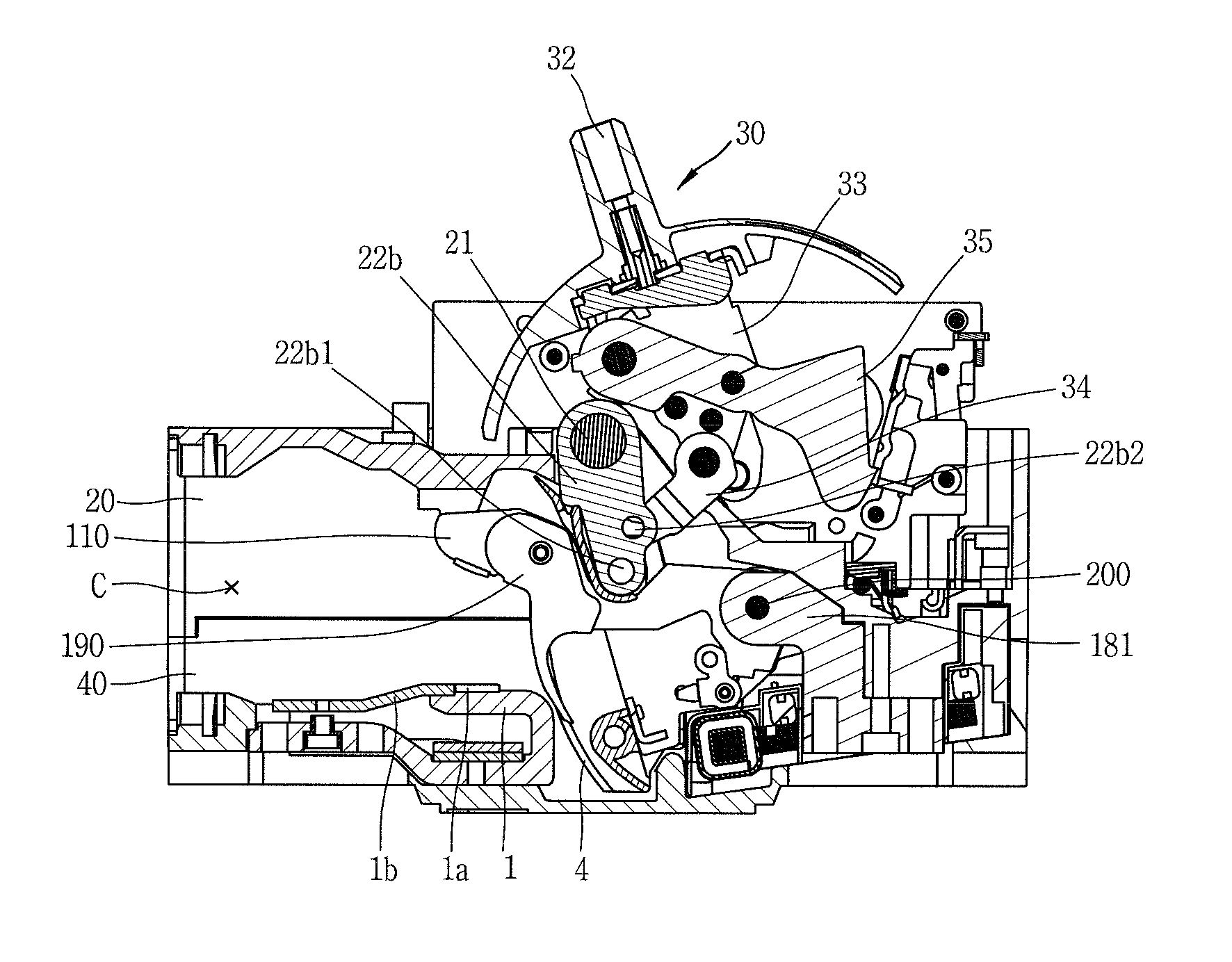
[0055]With reference to FIGS. 4 to 6, the current limiting type MCCB according to an preferred embodiment is configured to comprise, starting from the element positioned at the top, a switching mechanism 30, a shaft 21, links 6, 22a, 22b, and 22c, a movable contactor 110, a lower arc shielding plate 3, holders ...


PUM


Abstract

A movable contactor assembly for a current limiting type MCCB comprising: a terminal base fixedly installed on a case; a plurality of movable contactors having a cam face portion; a pair of holder plates supporting the movable contactors at both sides thereof; a plurality of first springs providing an elastic force to the movable contactors; a plurality of extending plate portions provided to face the side of one end portion of each of the movable contactors; a plurality of flexible wire plates electrically connecting the movable contactors and the terminal base and having a portion bendable toward the movable contactors or toward the extending plate portions; and a second spring providing an elastic force to the flexible wire plates so as to be tightly attached to the movable contactor.

Description

CROSS-REFERENCE TO A RELATED APPLICATION[0001]Pursuant to 35 U.S.C. §119(a), this application claims the benefit of earlier filing date and right of priority to Korean Application 10-2010-005322, filed on Jan. 20, 2010, the content of which is incorporated by reference herein in its entirety.BACKGROUND OF THE DISCLOSURE[0002]1. Field of the Invention[0003]The present invention relates to a molded case circuit breaker (abbreviated as MCCB hereinafter) and, more particularly, to a large capacity movable contactor assembly for a current limiting type MCCB having a plurality of contacts for each phase (pole).[0004]2. Description of the Related Art[0005]In general, a MCCB is an electric device for protecting an electrical load and an electric circuit by breaking a fault current, such as an overcurrent, an instantaneous large current, or a short-circuit current that occurs in the electric circuit between an electric power source and the electrical load.[0006]In particular, a large capacit...

Claims


Application Information

Patent Timeline
Patent Type & Authority Applications(United States)
IPC IPC(8): H01H75/10
CPCH01H77/10H01H1/226H01H77/104
Inventor BAEK, KI HO
Owner LS IND SYETEMS CO LTD
Why Eureka
Try Eureka