Image projection device
- Summary
- Abstract
- Description
- Claims
- Application Information
AI Technical Summary
Benefits of technology
Problems solved by technology
Method used
Image

Examples
first embodiment
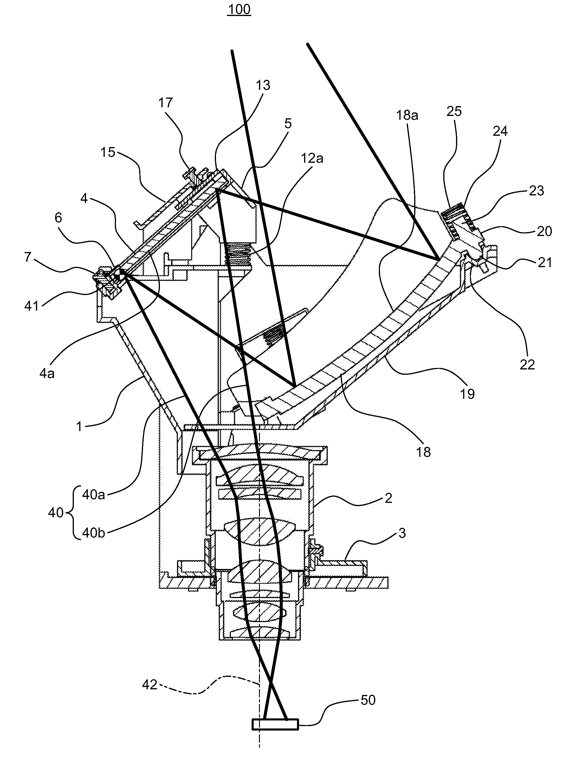
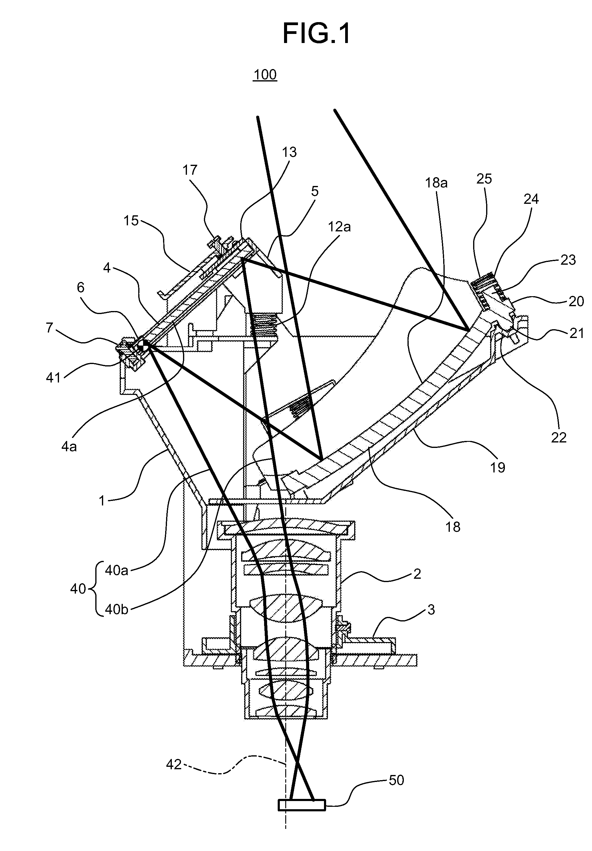
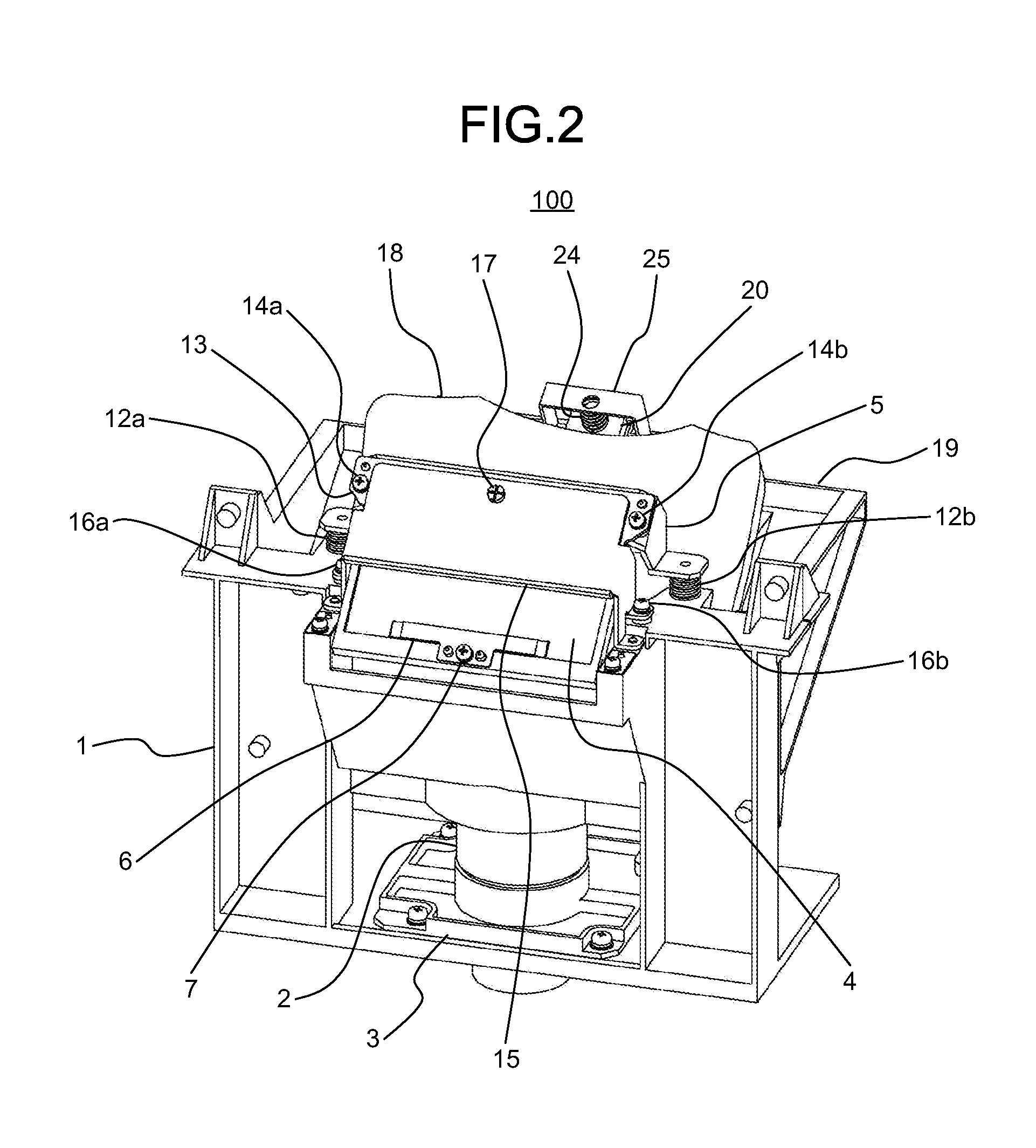
[0033]The mirror adjusting mechanism according to the first embodiment is explained below with reference to the drawings. FIG. 1 is a sectional view for showing an optical projection system 100 that includes the mirror adjusting mechanism according to the present embodiment, and FIG. 2 is a perspective view thereof. As illustrated in FIGS. 1 and 2, the optical projection system 100 includes a base member 1 that holds the components; a projection lens 2 that magnifies a light beam 40; a flange 3 that holds the projection lens 2 and is fixed to the base member 1; a flat mirror 4 that reflects the light beam 40 coming from the projection lens 2 and changes its direction; a holder for the flat mirror 5 that serves as a supporting unit for the flat mirror 4; a rotation axis 41 that serves as a central axis for the rotation of the holder for the flat mirror 5; a plate spring 6 that urges the flat mirror 4 toward the holder for the flat mirror 5; a screw 7 that fastens the plate spring 6; ...
second embodiment
[0061]FIG. 18 is a diagram of the structure of an image projection device 500 incorporating the mirror adjusting mechanism according to the first embodiment of the present invention. The image projection device 500 is a rear projection television that projects the light beam 40 from the back side of the screen 300 and displays an image. It includes an optical illumination system 150 that is simplified in the drawing, the optical projection system 100 connected thereto, the top panel mirror 200 arranged above the optical projection system 100, the screen 300 arranged on the front surface of the image projection device 500 to present the image, and a housing 400 that contains the structural components.
[0062]A light beam 52 emitted from a lamp 51 that is a light source is gathered by a relay lens 53, and reflected from three mirrors 54, 55, and 56 so that the reflective light modulating device 50 such as a DMD can be illuminated. The light beam 40 reflected from the reflective light mo...
third embodiment
[0066]FIG. 19 is a diagram for showing the structure of an image projection device 510 incorporating the mirror adjusting mechanism according to the first embodiment of the present invention. The image projection device 510 is a front-type projector that projects the light beam 40 directly onto a screen 310 and displays an image. It includes an optical illumination system 151 that is simplified in the drawing, the optical projection system 100 connected thereto, the reflective screen 310 on which an image projected from the image projection device 510 is projected, a housing 410 that contains the structural components, and a window 411 in the top surface of the housing 410 through which the light beam 40 passes. According to the present embodiment, the top panel mirror 200 arranged in the structures of the first and second embodiments is not included, and the light beam 40 is projected from the optical projection system 100 directly onto the screen 310.
[0067]The light beam 52 emitte...
PUM
 Abstract
Description
Claims
Application Information
 - Generate Ideas
- Intellectual Property
- Life Sciences
- Materials
- Tech Scout
- Unparalleled Data Quality
- Higher Quality Content
- 60% Fewer Hallucinations
Browse by: Latest US Patents, China's latest patents, Technical Efficacy Thesaurus, Application Domain, Technology Topic, Popular Technical Reports.
© 2025 PatSnap. All rights reserved.Legal|Privacy policy|Modern Slavery Act Transparency Statement|Sitemap|About US| Contact US: help@patsnap.com