Input parasitic metal detection

a technology of input parasitic metal detection and power loss accounting, which is applied in non-electric variable control, process and machine control, instruments, etc., can solve the problems of increased ohmic losses and difficulty in distinguishing

Active Publication Date: 2011-08-11
PHILIPS IP VENTURES BV
View PDF18 Cites 213 Cited by
  • Summary
  • Abstract
  • Description
  • Claims
  • Application Information

AI Technical Summary

Benefits of technology

[0011]These and other features of the invention will be more fully understood and

Problems solved by technology

It can be difficult to distinguish between losses resulting in increased ohmic losses due to misalignment and losses due to parasitic metal in the fie

Method used


Image

  • Input parasitic metal detection
  • Input parasitic metal detection
  • Input parasitic metal detection

Examples


Embodiment Construction

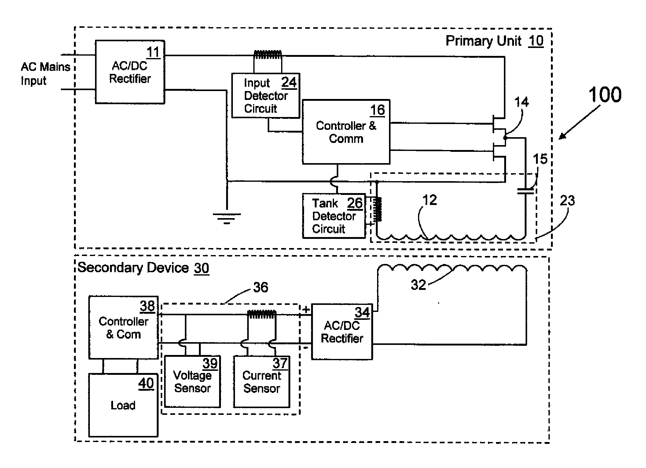
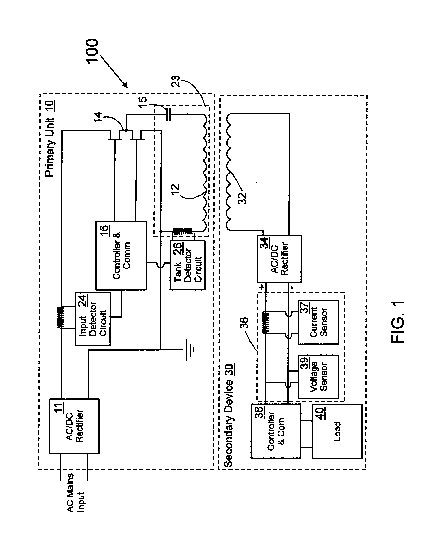
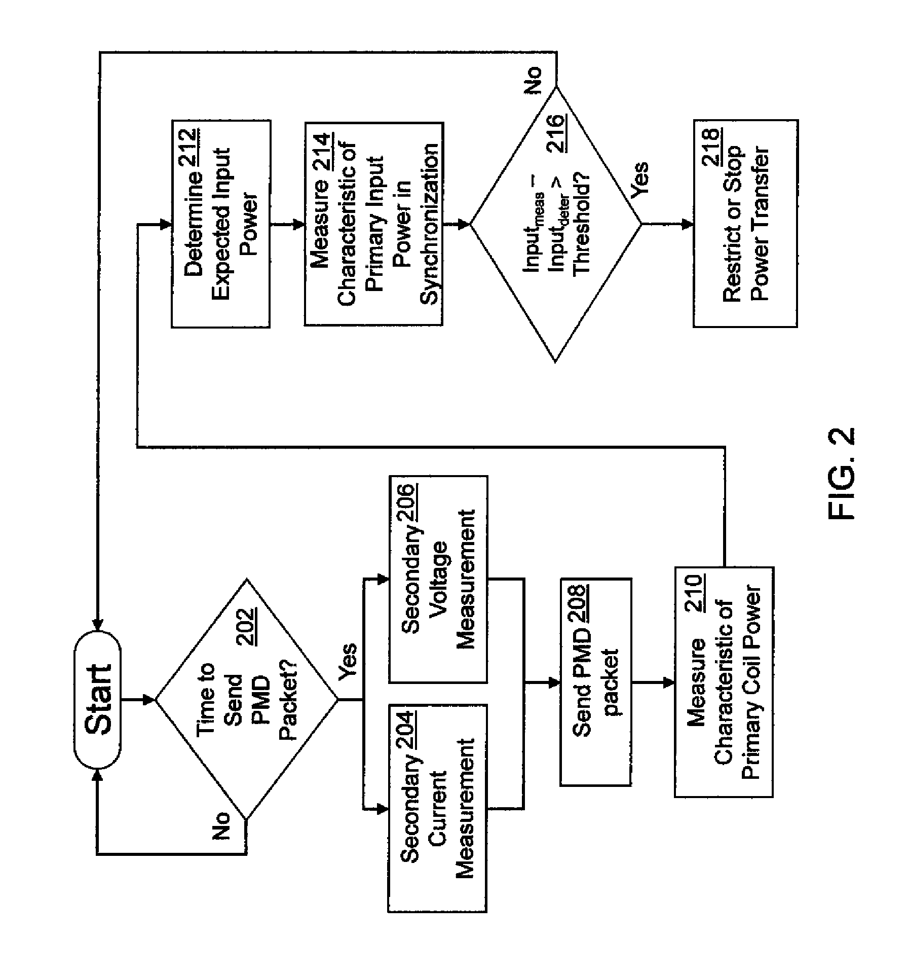
[0017]The present invention is directed to systems and methods for accounting for power loss in the system and understanding whether unaccounted for losses are detrimental to operation. For example, their may be parasitic metal, a damaged component, or something else in the electromagnetic field causing power loss. In one embodiment, primary coil current, secondary current, and secondary voltage are utilized to determine an expected primary input current. When the expected primary input current is properly determined, it can be compared to the measured primary input current in order to detect whether and in some embodiments, how much, unaccounted power loss is present.

[0018]Input current varies with the power lost or consumed in the contactless power supply system. For example, the input current is affected by parasitic metal losses, the amount of power delivered to the load, primary and secondary rectification losses, primary switching losses, losses in the tank circuit, losses due...


PUM


Abstract

A system and method of controlling inductive power transfer in an inductive power transfer system and a method for designing an inductive power transfer system with power accounting. The method of controlling inductive power transfer including measuring a characteristic of input power, a characteristic of power in the tank circuit, and receiving information from a secondary device. Estimating power consumption based on the measured characteristic of tank circuit power and received information and comparing the measured characteristic of input power, the information from the secondary device, and the estimated power consumption to determine there is an unacceptable power loss. The method for designing an inductive power transfer system with power accounting including changing the distance between a primary side and a secondary side and changing a load of the secondary side. For each distance between the primary side and the secondary side and for each load, measuring a circuit parameter on the primary side in the tank circuit and a circuit parameter on the secondary side during the transfer of contactless energy. The method further including selecting a formula to describe power consumption in the system during the transfer of contactless energy based on coefficients and the circuit parameters, and determining the coefficients using the measured circuit parameters.

Description

FIELD OF THE INVENTION[0001]The present invention relates to power loss accounting for a contactless power supply system.BACKGROUND OF THE INVENTION[0002]It is becoming more common for contactless power to be transmitted to portable electronic devices, for example by utilizing inductive coupling. Many inductive power supply systems suitable for powering portable devices include two main components: (1) an inductive power supply or primary unit having at least one primary coil, through which it drives an alternating current, creating a time-varying electromagnetic field, and (2) a portable electronic device or secondary device, separable from the primary unit, including a secondary coil, which when placed in proximity to the time-varying field, the field induces an alternating current in the secondary coil, thereby transferring power from the primary unit to the secondary unit.[0003]Contactless power supply systems are not 100% efficient. That is, some energy is lost in order to tran...

Claims


Application Information

Patent Timeline
IPC IPC(8): G06F1/28
CPCH01F38/14H02J5/005H02J7/0047H02J50/90H02J50/12H02J50/60H02J50/70H02J7/025G01R21/00G01V3/02H02J50/005
Inventor BAARMAN, DAVID W.SCHWANNECKE, JOSHUA K.KUYVENHOVEN, NEIL W.UMENEI, A. ESAILIFF, DALE R.ZEIK, ANDREW C.BLAHA, MARK A.AMISTADI, JASON L.GRUICH, ROBERT D.
Owner PHILIPS IP VENTURES BV
Why Eureka
Try Eureka