
Sliding window or sliding glass door

a sliding glass door and window technology, applied in the direction of door/window fittings, wing accessories, wing arrangements, etc., can solve the problems of deficient devices, difficulty in guiding the large-dimension panels, and increased handling forces during opening and closing of windows

Inactive Publication Date: 2011-08-18
ORCHIDEES CONSTR
View PDF10 Cites 11 Cited by
  • Summary
  • Abstract
  • Description
  • Claims
  • Application Information

AI Technical Summary

Benefits of technology

[0006]The said lower side of the frame can have a longitudinal covering profiled part with an inverted U-shaped profile placed on two seats of an assembly of two profiled parts forming the structure of the said lower element of the frame, the guides being fixedly attached to this covering profiled part by transverse pins and these pins being dimensioned so that the placement of the covering profiled part between parallel sides, each provided with an internal longitudinal rib of the said profiled part assembly, permits longitudinal guidance of the panel in its plane of symmetry during sliding.

Problems solved by technology

Thus, this trend leads to an increase in handling forces during opening and closing of the window.
One of the additional difficulties resides in guiding the large-dimension panels which frequently have a natural curvature originating in the manufacturing process.
For large-dimension glazing units, these devices are deficient because they do not allow correction for the natural curvatures of the glass.

Method used


Image

  • Sliding window or sliding glass door
  • Sliding window or sliding glass door
  • Sliding window or sliding glass door

Examples


Embodiment Construction

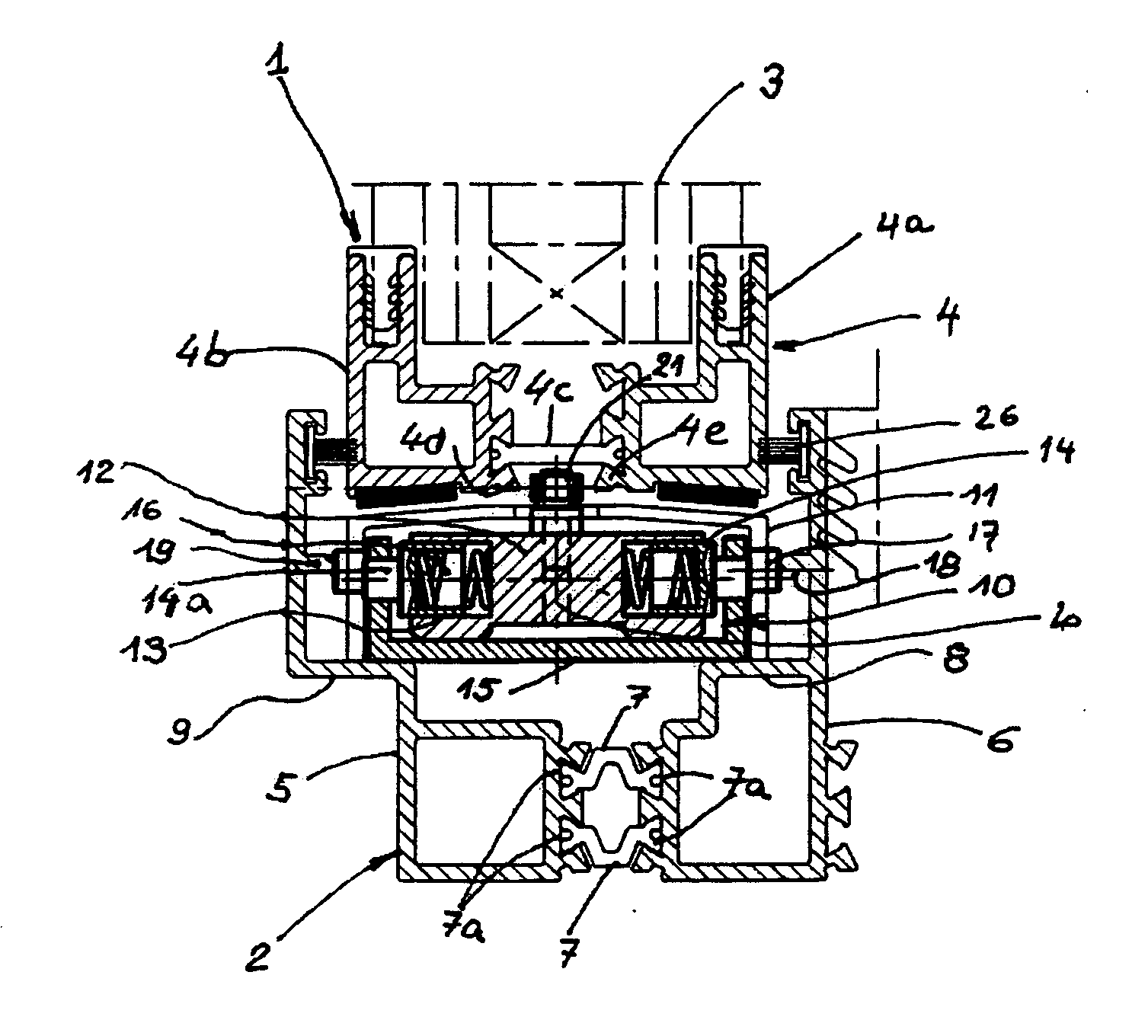
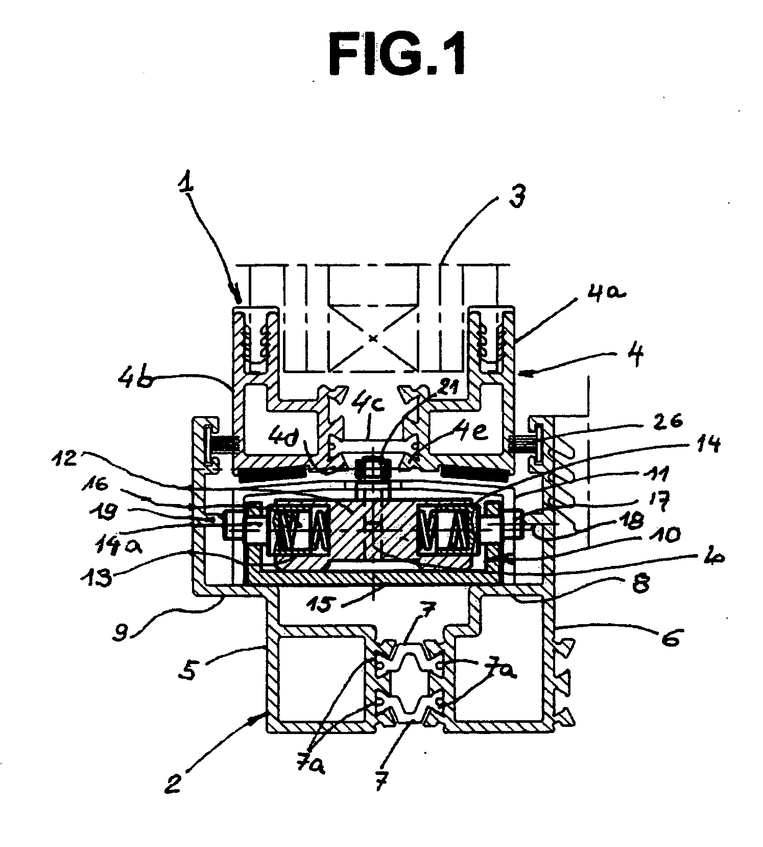
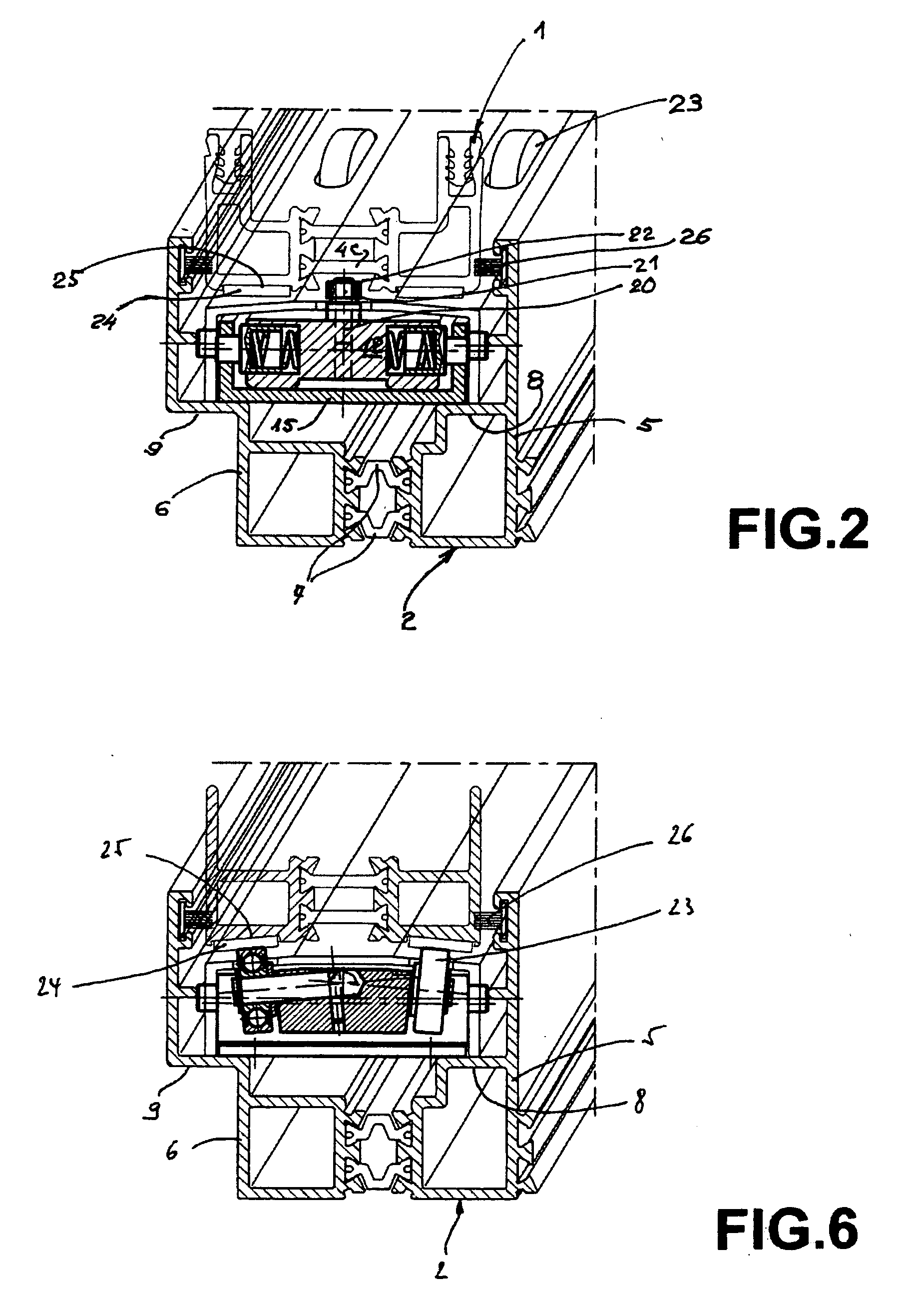
[0018]FIG. 1 shows a partial view of the rectangular glazed panel 1 of a sliding window mounted in a fixed frame 2. The figure shows the bottom of the window, the glazed assembly 3 of which is equipped with a rigid reinforcing member 4 formed from metal profiled parts (4a and 4b). The glazed assembly 3 can have any of the various following structures: one or several plates of glass, plates spaced apart or placed side by side, of the same structure or of different structures, etc. The member 4 may be fitted to only the lower border of the glazing unit 3 but can also surround it entirely or only on its upper and lower borders. It is formed from segments of straight aluminum profiled parts. It will be noted that the reinforcing member 4 has in particular two straight segments 4a and 4b of profiled parts in the general form of a right angle, which are connected to each other by a polyimide thermal break 4c. Furthermore, portions of the profiled parts 4a and 4b which extend projecting do...


PUM


Abstract

The sliding panel (1) comprise on at least one of sides thereof in the direction of the movement thereof, the reinforcing member (4) consisting of two aluminum sections (4a and 4b) connected by a polyamide thermal break (4c) and having two edges (4d and 4e) that define the longitudinal groove (22) having the same width from one end of the member (4) to the other end thereof. The guides (10) and the longitudinal inverted channel section (11) are placed in stationary positions on the benches (8 and 9) belonging to the profile sections of the frame (2) of the sliding window or sliding glass door. Each guide (10) comprises, in the center of the block (12), the vertical rod (20) having, on the top end thereof, ball bearings (21) that are located exactly between the edges (4d and 4e) and are located in the longitudinal channel (22) through which the panel (1) is guided in the movements thereof.

Description

TECHNICAL FIELD[0001]The present invention relates to a sliding window or sliding glass door having a fixed frame and, in this frame, at least one glazed panel which cooperates with guide means associated with the frame and guiding the panel so as to move along the frame.STATE OF THE ART[0002]Windows or glass doors of this type are already known, in particular by the disclosure of patent CH 696 444, CH 390 511 or the international publication WO 94 / 17275, the latter being by the same applicant. The current architectural trend in the area of windows demands large glazing dimensions as well as high levels of acoustic and thermal performance. In order to meet these requirements the glazing units are becoming larger and larger and heavier and heavier. Thus, this trend leads to an increase in handling forces during opening and closing of the window. One of the additional difficulties resides in guiding the large-dimension panels which frequently have a natural curvature originating in th...

Claims


Application Information

Patent Timeline
IPC IPC(8): E05D15/06E06B3/46
CPCE05D15/0665E05D15/0686E06B3/4609E05Y2900/132E06B3/26347E05Y2800/672
Inventor JORAY, ERIC
Owner ORCHIDEES CONSTR
Learn More