Digital angle gauge

a digital angle and gauge technology, applied in the field of digital angle gauges, can solve the problems of cumbersome and accurate setting of difficult to view and read clearly from above and/or peripherally, and difficult to reliably press the push buttons that operate the gauge on the front face of the gauge, etc., and achieve the effect of much more convenient and clear viewing

Active Publication Date: 2011-08-18
WIXEY BARRY DOUGLAS
View PDF41 Cites 13 Cited by
  • Summary
  • Abstract
  • Description
  • Claims
  • Application Information

AI Technical Summary

Benefits of technology

[0006]It is therefore an object of the present invention to provide an improved digital angle gauge that allows inclination angles to

Problems solved by technology

The viewing screen is invariably oriented perpendicular to the ground and can be difficult to view and read clearly from above and/or peripherally.
By the same token, positioning the push buttons that operate the gauge (for example the ON/OFF and ZERO reference buttons) on the front face of the gauge can be problematic.
It can be cum

Method used


Image

  • Digital angle gauge
  • Digital angle gauge
  • Digital angle gauge

Examples


Embodiment Construction

[0018]Other objects, features and advantages will occur from the following description of a preferred embodiment and the accompanying drawings, in which:

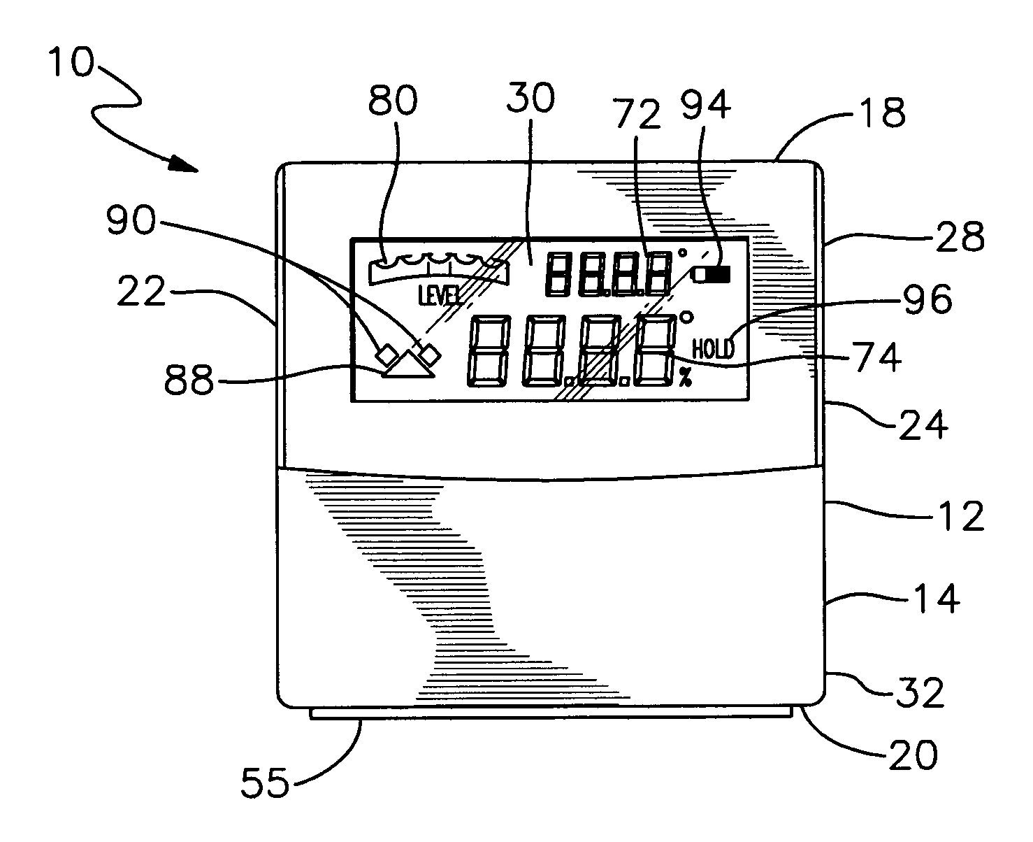
[0019]FIG. 1 is a front elevational view of a preferred digital angle gauge in accordance with this invention;

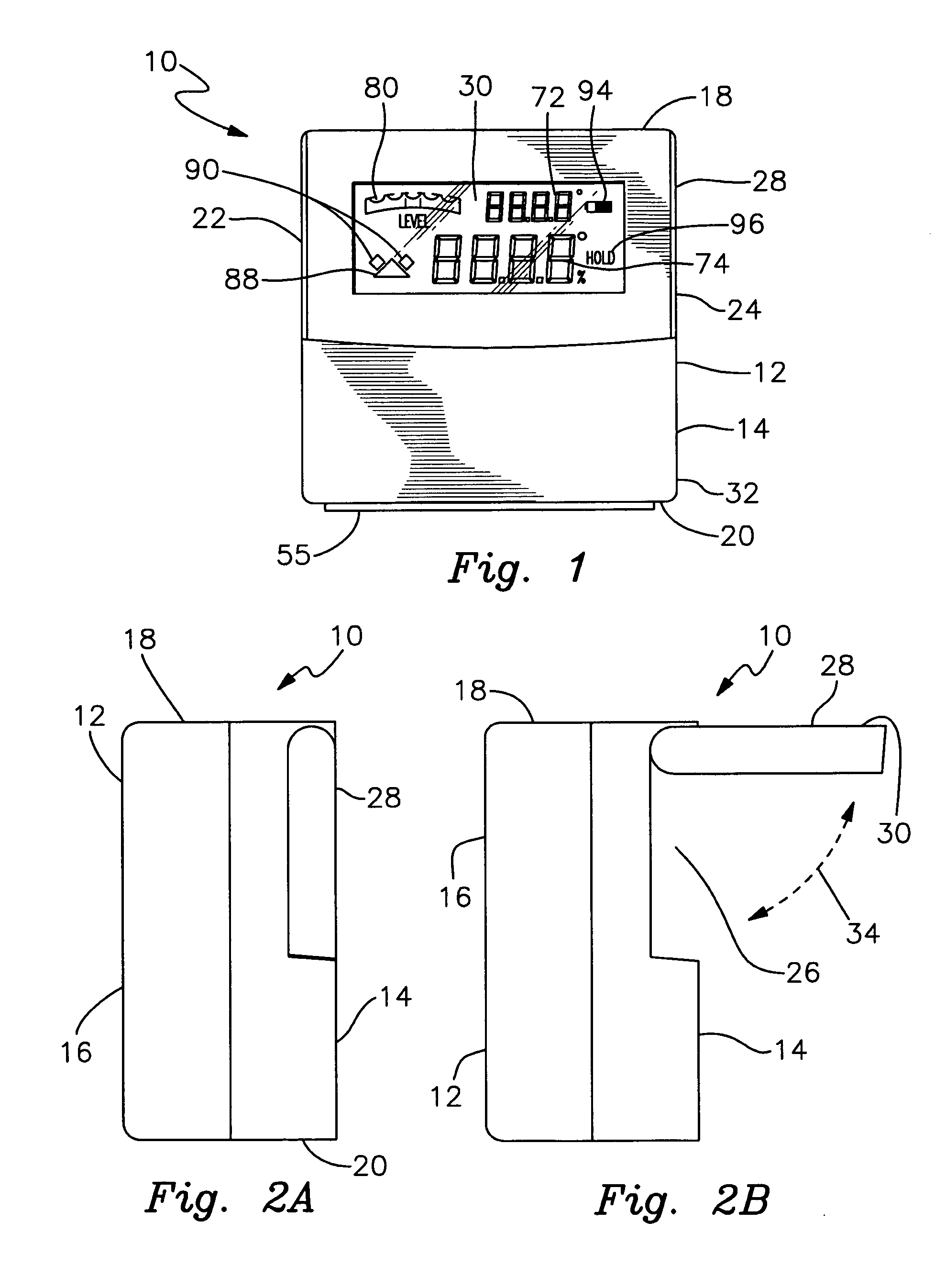
[0020]FIG. 2 is a top perspective view of the digital angle gauge;

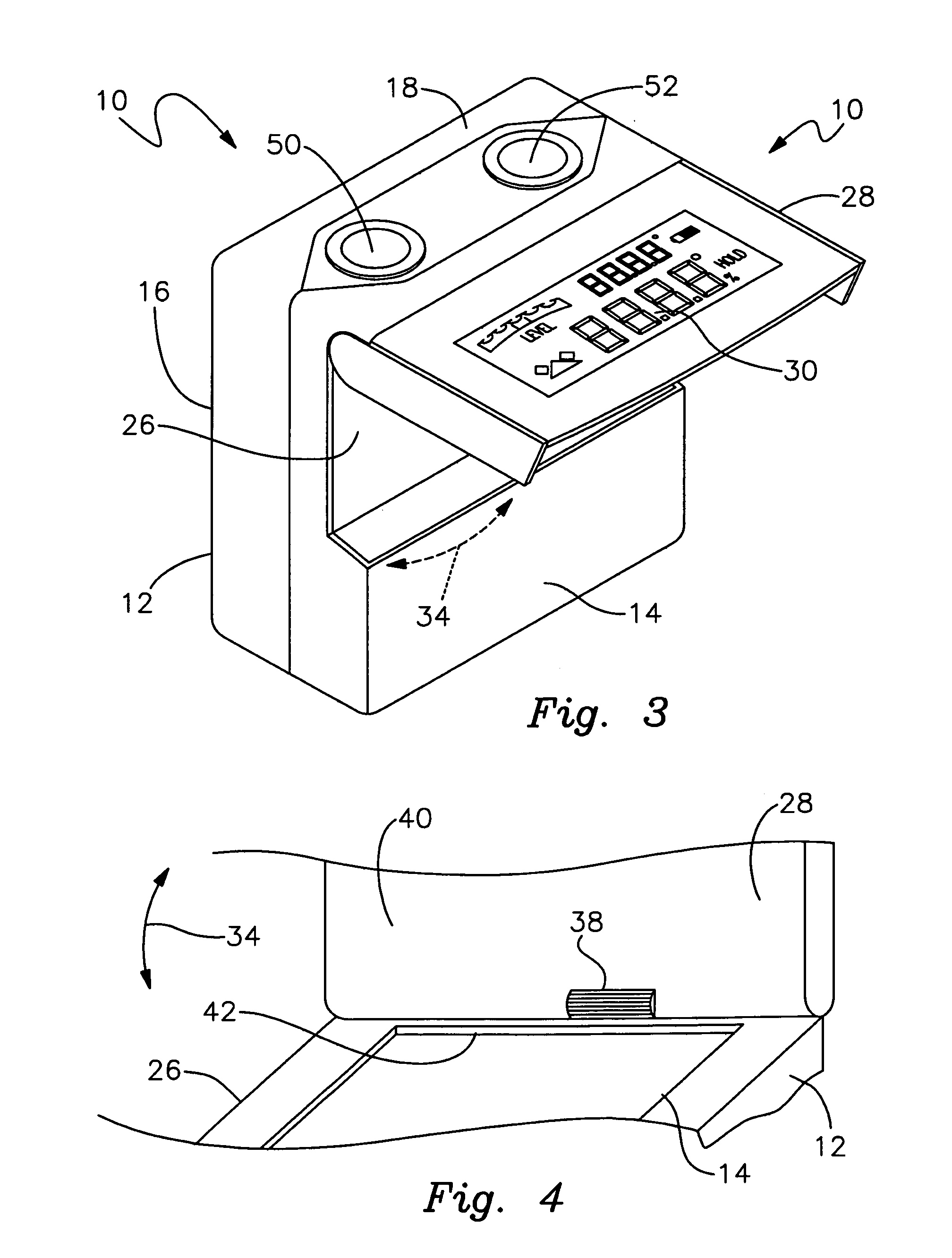
[0021]FIG. 3 is a top perspective view of the digital angle gauge, with the pivoting screen in an open condition extending substantially perpendicular to the gauge body;

[0022]FIG. 4 is a perspective fragmentary view of the underside of the display screen in an open condition relative to the gauge body and particularly depicting the angle retention cam that holds the display screen in a selected angle relative to the gauge body.

[0023]FIG. 5 is a schematic view depicting the principle electrical components of the gauge;

[0024]FIGS. 6A-6E are elevational views of respective absolute angle readings provided by the intuitive “bubble level” graphic display used in th...


PUM


Abstract

A digital angle gauge includes a gauge body having a reference surface that is engageable with an object to be measured for angular inclination. An angle sensor and processor mounted in the body determine an inclination angle of the object with which the reference surface of the gauge body is engaged. A digital screen is pivotally mounted to the gauge body for visually displaying the determined inclination.

Description

RELATED APPLICATION[0001]This application claims the benefit of U.S. Provisional Patent Application Ser. No. 61 / 338,360 filed Feb. 17, 2010.FIELD OF THE INVENTION[0002]This invention relates to a digital angle gauge, and particularly to an inclinometer type angle gauge featuring a pivoting display screen and operating buttons positioned conveniently on the top face of the device. The digital screen simultaneously displays absolute and incremental numerical measurements accompanied by an intuitive angular display graphic.BACKGROUND OF THE INVENTION[0003]Various digital angle gauges are currently available for measuring the tilt or inclination of an object or a work surface. Inclinometer-type angle gauges typically feature a generally rectilinear configuration. A digital display screen and operating buttons are mounted on a vertical front face of the device. At least one side surface of the inclinometer functions as a reference surface for engaging the work surface or object to be mea...

Claims


Application Information

Patent Timeline
IPC IPC(8): G01C9/06G01C25/00
CPCG01C9/06G01B5/24G01B3/56
Inventor WIXEY, BARRY DOUGLASJIAN, SHIJIN, LI GUANG
Owner WIXEY BARRY DOUGLAS
Why Eureka
Try Eureka