

Composite pipe for high-pressure gas and a manufacturing method of the same
Inactive Publication Date: 2011-08-18
MEGA PIPE CO LTD
View PDF1 Cites 6 Cited by
- Summary
- Abstract
- Description
- Claims
- Application Information
AI Technical Summary
Benefits of technology
[0051]As described above, the composite pipe for replacing carbon steel pipes for ordinary piping and pressure service or air-conditioner copper pipes can replace a high-priced copper pipe by using plastic which has not been used in the sector of air-conditioners. Without using an adhesive, the chemical and physical properties of the first resin layer, the first bonding layer, the metal layer, the second bonding layer, and the second resin layer of the composite pipe are integrated through reactions therebetween, whereby an internal bonding force (interlayer radical bonding force) according to the chemical bonding can be increased by more than 40 kgf/cm2, the ultimate tensile strength pressure degree with respect to pressure can be increased from 10 kgf
Problems solved by technology
However, in addition to the shortcomings of the high price, the copper pipe has problems in that a high contraction and expansion rate at a connector part degrades gas preservation characteristics, and when the copper pipe is used for a long period of time, scale is formed thereon, so the copper pipe needs to be replaced at a certain time point.
In that case, scale is generated due to
Method used
View moreImage
Smart ImageViewing Examples


Examples
 PUM
| Property | Measurement | Unit |
|---|---|---|
| Temperature | aaaaa | aaaaa |
| Temperature | aaaaa | aaaaa |
| Temperature | aaaaa | aaaaa |
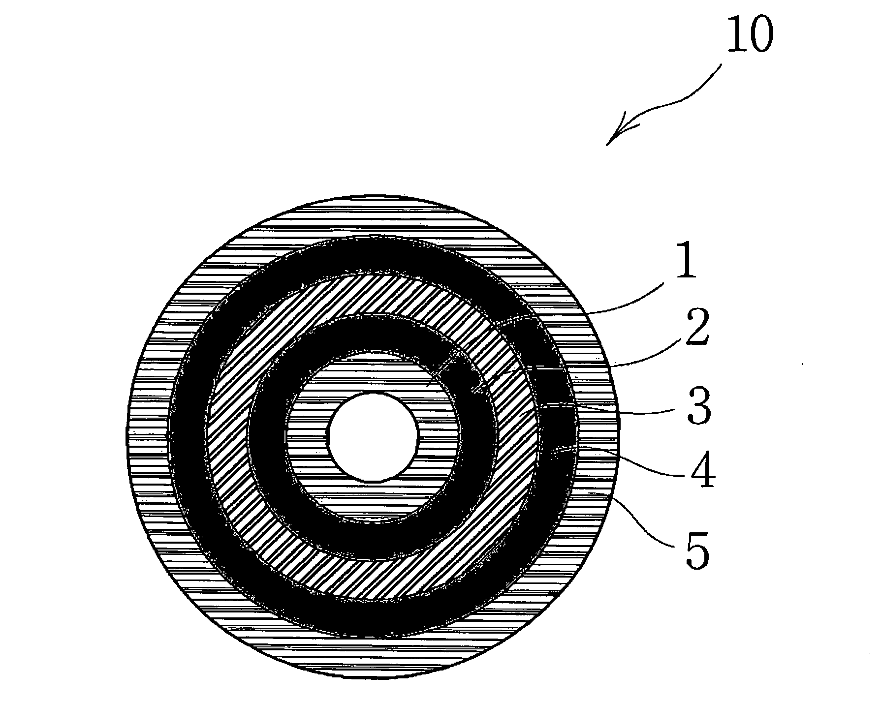
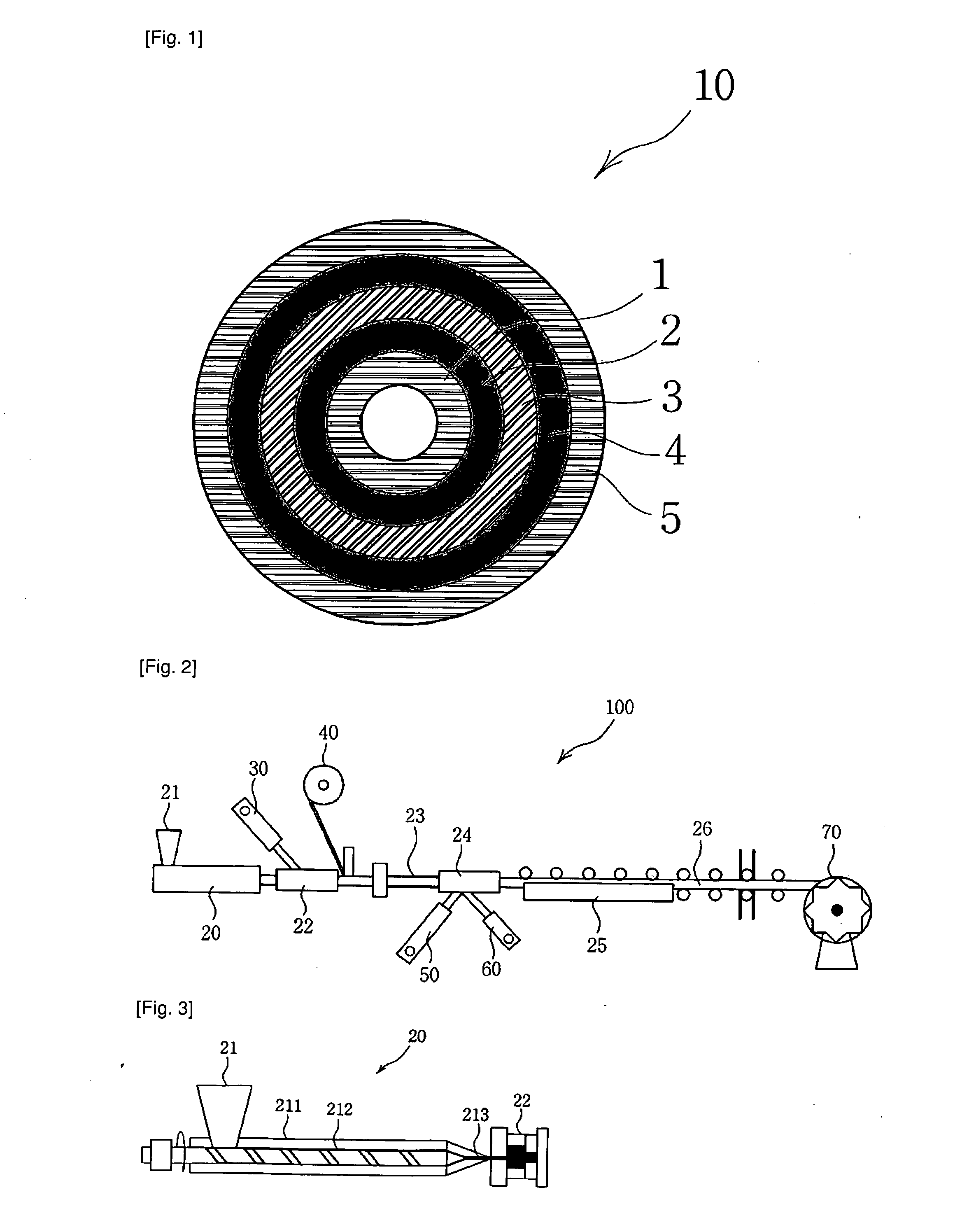
Abstract
A composite pipe and a manufacturing method for the same are disclosed. The composite pipe for replacing carbon steel pipes for ordinary piping or copper pipes for air-conditioner includes: a first resin layer (1) formed by cross-linking a resin and giving a polar group thereto; a first bonding layer (2) for inducing bonding by sharing radical groups of the first resin layer and a metal layer; the metal layer (3); a second bonding layer (4) for inducing bonding by sharing radical groups of the metal layer; and a second resin layer (5) formed by cross-linking a resin and giving a polar group thereto, thereby integrating the layers chemically and physically.
Description
TECHNICAL FIELD[0001]The present invention relates to a plastic and metal composite pipe to reply e a copper pipe made of high-priced copper and used for carbon steel pipes for ordinary piping and pressure service or air-conditioner copper pipes.BACKGROUND ART[0002]High-priced copper pipes have been used for air-oonditioners because of the characteristics of high pressure resistance, durability heat resistance, anti-chemical charcteristics and bending radius properties of the pipes made of copper.[0003]However, in addition to the shortcomings of the high price, the copper pipe has problems in that a high contraction and expansion rate at a connector part degrades gas preservation characteristics, and when the copper pipe is used for a long period of time, scale is formed thereon, so the copper pipe needs to be replaced at a certain time point.[0004]In case of an alternative pipe made of a mixed material of magnesium and aluminum which has been proposed to replace the conventional, c...
Claims
Login to View More Application Information
Patent Timeline
 IPC IPC(8): F16L9/14B29C47/04B32B37/02B32B37/12B32B37/24B29C48/09
CPCB29C47/0023B29C47/1054B29C47/065B29C47/10B29C47/1018B29C47/261B29C47/82B29C47/822B29C2947/9259B29C2947/92695B29C2947/92704B29C2947/92809B29C2947/92828B29C2947/92838B29C2947/92885B29C2947/92904B29K2009/06B29K2021/00B29K2023/06B29K2023/12B29K2023/16B29L2009/003B29L2023/22F16L9/147B29C47/1009B29C47/021B29C48/83B29C48/865B29C2948/92704B29C48/09B29C48/151B29C48/21B29C48/285B29C48/286B29C48/287B29C48/2888B29C48/336B29C48/793B29C48/832B29C2948/9259B29C2948/92695B29C2948/92809B29C2948/92828B29C2948/92838B29C2948/92885B29C2948/92904
InventorIM, GWAN U
OwnerMEGA PIPE CO LTD