Brushless DC motor

a brushless dc motor and motor body technology, applied in the direction of dynamo-electric machines, electrical equipment, supports/enclosements/casings, etc., can solve the problems of complex connection structure of the end of the coil wound around the terminal with respect to the substrate, and the inability to easily form the radial protrusion which can be automatically wound with the coil, so as to achieve accurate and reliable electrical connection of the coil to the substrate

Inactive Publication Date: 2011-08-18
MINEBEA CO LTD
View PDF13 Cites 9 Cited by
  • Summary
  • Abstract
  • Description
  • Claims
  • Application Information

AI Technical Summary

Benefits of technology

[0025]According to the seventh aspect of the present invention, electrical connecting of the coil to the substrate can be accurately and reliably performed by using the land.

Problems solved by technology

According to conventional methods, the connecting structure of the end of the coil wound around the terminal with respect to the substrate is complicated.
The reason for this is that, in the above condition, a small Brush DC motor is restricted to have a radially sufficient space and the radial protrusion which can be automatically wound with the coil cannot be easily formed.

Method used


Image

  • Brushless DC motor
  • Brushless DC motor
  • Brushless DC motor

Examples


Embodiment Construction

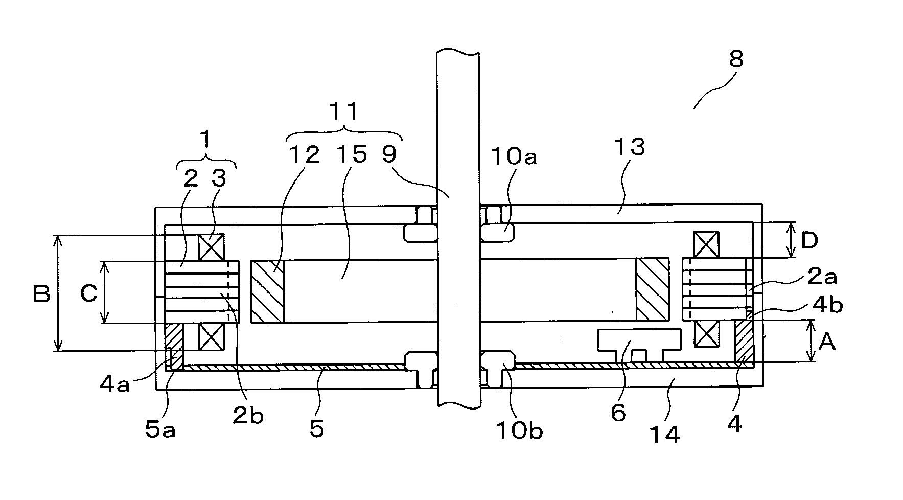
[0032]FIG. 1 is a cross-sectional view of a brushless DC motor in accordance with an embodiment of the present invention. The brushless DC motor 8 in accordance with the embodiment is shown in FIG. 1. The brushless DC motor 8 is provided with a shaft 9. A holding member 15 having a disc-shaped structure is fixed to the shaft 9, and a circumferential portion thereof is multiply magnetized, whereby a permanent magnet 12 used as a rotor magnet is formed. A rotor 11 is composed of the shaft 9, the holding member 15 and the permanent magnet 12.

[0033]The shaft 9 of the rotor 11 is rotatably held with respect to an upper housing 13 by a bearing 10a and is rotatably held with respect to a lower housing 14 by a bearing 10b. By this structure, the rotor 11 is rotatable with respect to the upper housing 13 and the lower housing 14.

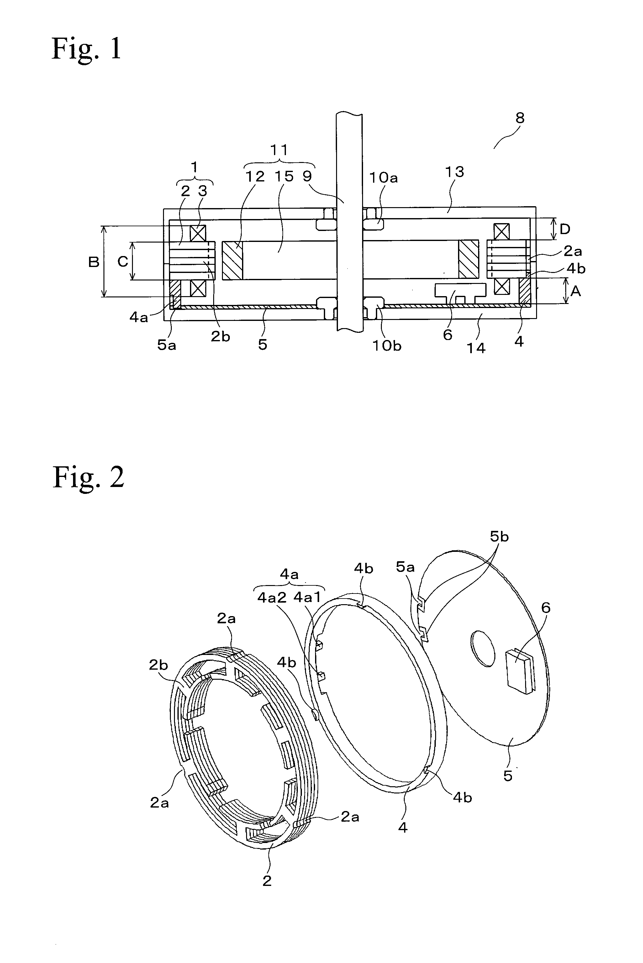
[0034]The upper housing 13 and the lower housing 14 are integrally fixed to each other and form a housing of the brushless DC motor. A stator core 2 is held in the i...


PUM


Abstract

A brushless DC motor includes a housing having an upper and a lower housings, a stator including a stator core and a coil wound around the stator core, a rotor rotatably disposed in the stator, an annular terminal block disposed at an axial side of the stator and having an axially protruding terminal connected to an end of the coil, a disc-shaped substrate holding the annular terminal block with the stator and having a sensor IC and a driving circuit, the substrate provided with a fitting portion closely fitted by the terminal, wherein the terminal of the terminal block is closely fitted into the fitting portion of the substrate and the end of the coil is electronically connected to the substrate via a portion in which the end of the coil is connected to the terminal.

Description

RELATED APPLICATIONS[0001]This application claims priority under 35 U.S.C. §119 to Japanese Patent Application No. 2010-029669 filed on Feb. 15, 2010, the entire content of which is hereby incorporated by reference.BACKGROUND OF THE INVENTION[0002]1. Field of the Invention[0003]The present invention relates to a brushless DC motor provided with a coil having an end portion with a specific connecting structure.[0004]2. Related Art[0005]Some kinds of brushless DC motors, in which a disc-shaped substrate having a sensor IC and a driving circuit is provided on an axial one side surface of a stator wound with a coil, are known. In this structure, a method for connecting an end of a coil wound around a terminal of an insulator to the substrate is complicated, and positioning of the substrate with respect to the stator and the sensor IC is required. Furthermore, after the winding operation, the end of the coil must be connected to a part of the substrate, whereby many operating steps are r...

Claims


Application Information

Patent Timeline
Patent Type & Authority Applications(United States)
IPC IPC(8): H02K5/22
CPCH02K3/522H02K2213/03H02K29/08
Inventor NAKAMURA, MANABUSUZUKI, YUZURU
Owner MINEBEA CO LTD
Why Eureka
Try Eureka