Automatic screw-driving machine

An automatic locking screw machine and machine body technology, applied in metal processing, metal processing equipment, manufacturing tools, etc., can solve the problems of not meeting the actual process requirements, affecting the service life of components, and poor applicability

Active Publication Date: 2016-04-06
SHENZHEN XING GRAIN AUTOMATION CO LTD
View PDF8 Cites 18 Cited by
  • Summary
  • Abstract
  • Description
  • Claims
  • Application Information

AI Technical Summary

Problems solved by technology

In the actual assembly line production process, the PCB board is transported continuously on the assembly line, so the PCB board is required to be in a static state before the guide pin is fixed on the PCB board, and it is necessary to ensure that the PCB board does not swing during the fixing process; in addition, Due to the different width and size of various PCB boards in actual production, if a fixed material guide mechanism is used, only one type of PCB board can be processed, and the applicability of the equipment is poor, resulting in increased production costs
To realize the automatic fixation of guide pins to improve production efficiency and production quality, it is first necessary to have automatic transportation of guide pins. At present, the most commonly used material conveying devices in the machinery industry are generally vibrating discs, which can continuously vibrate materials without interruption. However, since the fixing process of the guide pin and the PCB board involves multiple process actions, each action takes a certain amount of time and is an intermittent action, so only feeding through the vibrating plate cannot meet the requirements of the guide pin fixing process. actual process needs
In addition, the continuous feeding mode of the vibrating plate of the guide pin cannot be smoothly connected with the rear-end ejecting mechanism, and the design structure of only the vibrating plate and the ejecting mechanism cannot guarantee the normal transportation of materials
In addition, during the ejection process, due to factors such as machining errors and assembly errors, position deviation may occur when the ejection mechanism ejects the guide pin upwards, resulting in the failure of the subsequent screw locking process to proceed normally; The downforce of the jacking mechanism is the main load-bearing part in the screw locking process. If the downforce is too large, it will cause damage to the parts of the jacking mechanism and affect the service life of the parts.

Method used


Image

  • Automatic screw-driving machine
  • Automatic screw-driving machine
  • Automatic screw-driving machine

Examples


Embodiment Construction

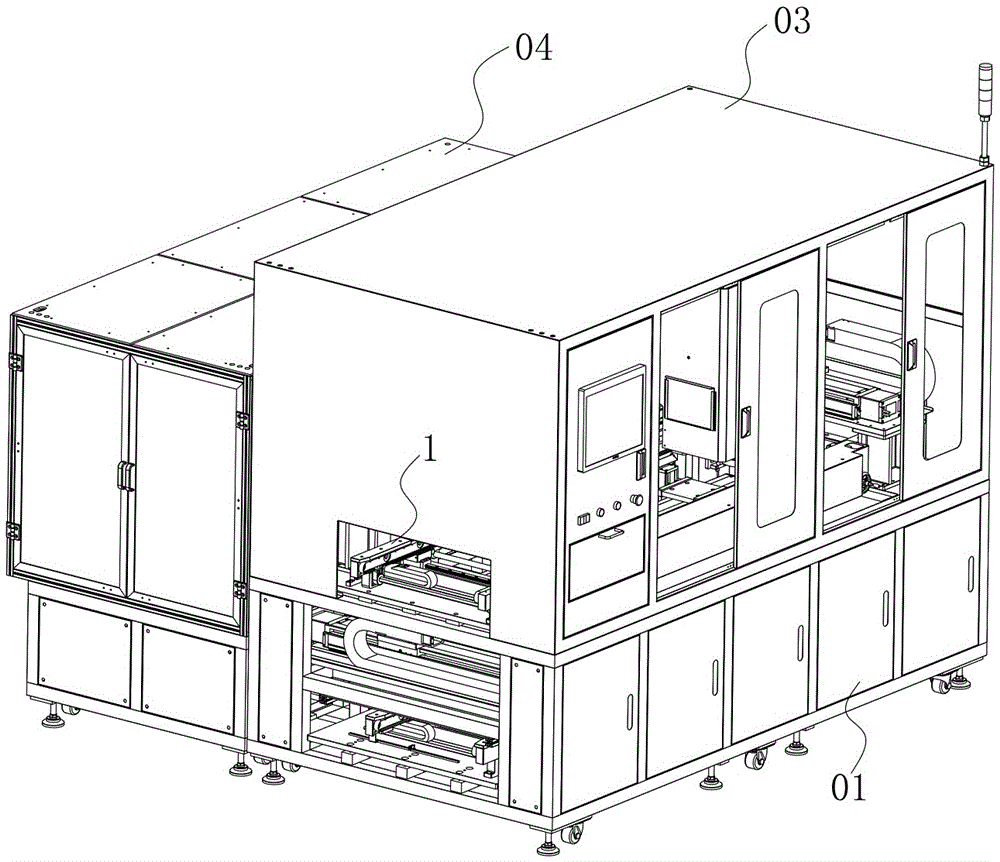
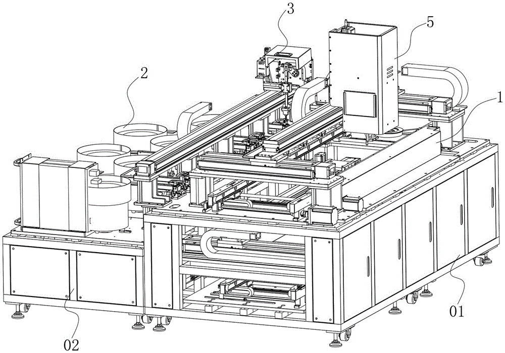
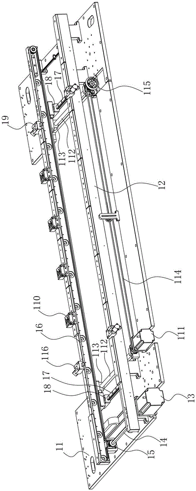
[0071] The present invention will be further described below in conjunction with accompanying drawing:

[0072] like Figure 1 to Figure 10 As shown, the technical solution adopted by the present invention is as follows: an automatic screw locking machine, comprising a body assembly, a material guide mechanism 1, a material transport mechanism 2, a material grasping mechanism 3, a material jacking mechanism 4 and a screw locking mechanism 5, wherein, The above-mentioned material guide mechanism 1 is arranged on the main frame 01 of the body assembly, and extends along the side direction of the main frame 01. The PCB board of the screw to be locked is transported forward on the material guide mechanism 1, and is positioned and fixed by its stopper positioning component PCB board; the material transport mechanism 2 is arranged on the sub-frame 02 positioned at one side of the main frame 01, and the material transport mechanism 2 includes at least two, so that the guide pin 05 of...


PUM


Abstract

The invention discloses an automatic screw-driving machine which comprises a machine body assembly, a material guide mechanism, a material conveying mechanism, a material grabbing mechanism, a material ejecting mechanism and a screw-driving mechanism. The material guiding mechanism is arranged on a main machine frame of the machine body assembly. The material conveying mechanism is arranged on an auxiliary machine frame on one side of the main machine frame. The material grabbing mechanism is arranged between the material conveying mechanism and the material guide mechanism and conveys guide pins to the material ejecting mechanism. The guide pins are conveyed to the position below PCBs through the material ejecting mechanism. The screw-driving mechanism is arranged above the material guiding mechanism and drives screws into the guide pins. The automatic screw-driving machine is suitable for a PCB automatic machining assembly line, the functions of automatically positioning blocking materials and adjusting the sizes of the conveyed PCBs are achieved through the material guide mechanism, the automatic material feeding or blocking movement is achieved through the material conveying mechanism, the automatic conveying movement of the guide pins is achieved through the material grabbing mechanism, the automatic material ejecting movement is achieved through the material ejecting mechanism, and nuts are automatically locked on the guide pins through the screw-driving mechanism.

Description

technical field [0001] The invention relates to the field of automatic machinery, in particular to an automatic screw locking machine. Background technique [0002] The guide positioning pin is used to limit and fix the PCB board in the equipment casing. It is a common PCB board accessory. When the guide pin is used, the guide positioning pin needs to be fixed on the PCB first, and then the guide pin is In the positioning hole of the casing, the PCB board can be positioned and fixed in the casing; the guide pin includes a guide rod connected to the lower part of the PCB board, a seat part and a detachable nut part, when the guide pin is fixed on the PCB board , first of all, it is necessary to place the guide rod and the base part on the lower part of the PCB board, align the screw holes of the base part with the through holes on the PCB board, and then pass the nut from the upper part of the through hole of the PCB board through the PCB board to connect and fix the base bod...

Claims


Application Information

Patent Timeline
Patent Type & Authority Applications(China)
IPC IPC(8): B23P19/06
CPCB23P19/001B23P19/004B23P19/06
Inventor 唐亮
Owner SHENZHEN XING GRAIN AUTOMATION CO LTD
Why Eureka
Try Eureka