
Liquid ejecting apparatus

Inactive Publication Date: 2011-08-18
SEIKO EPSON CORP
View PDF3 Cites 9 Cited by
  • Summary
  • Abstract
  • Description
  • Claims
  • Application Information

AI Technical Summary

Benefits of technology

[0011]An advantage of an aspect of the invention is that it provides a liquid ejecting apparatus that can preferably prevent an occurrence of liquid ejection failures.
[0013]According to the aspect of the invention, liquid can be prevented from flowing back along each flow path in a downstream side from a branch point serving as a reference in the liquid supplying flow path even when liquid is ejected from any of the liquid ejecting sections. In other words, even when liquid is ejected from any of the liquid ejecting sections, a liquid flow between the flow paths in the downstream side through the branch point can be prevented, and liquid can reliably flow from the flow path in the upstream side to the flow paths corresponding to the liquid ejecting sections ejecting the liquid in the downstream side through the branch point. Because of this structure, liquid in a liquid ejecting section that is not ejecting liquid or in a liquid ejecting section whose liquid ejection amount is small compared with that of other liquid ejection sections, can be prevented from being sucked up toward the side of a liquid ejecting section that is ejecting liquid or the side of a liquid ejecting section whose liquid ejection amount is large compared with that of other liquid ejecting sections. As a result, the occurrence of ejection failures can be preferably prevented.

Problems solved by technology

Because of this structure, for example, a problem arises in that when one of the recording heads is selectively cleaned, ink in each nozzle of other recording heads that are not subjected to cleaning is sucked up and drained into the recording head being cleaned since the recording heads communicate with each other through the branch point in the ink supplying flow path.
In addition, the line head printer has another problem in that when some recording heads are ejecting ink and other recording heads are not ejecting ink according to a fixed print pattern, ink in each nozzle of the recording heads that are not ejecting ink is sucked up and drained into the recording heads when ejecting ink in the same manner as when cleaning.
As a result, ink ejection failures occur when ink is ejected in subsequent printing from the nozzle from which ink has been drained.

Method used


Image

  • Liquid ejecting apparatus
  • Liquid ejecting apparatus
  • Liquid ejecting apparatus

Examples


modified examples

[0058]The above-described embodiment may be modified as follows.

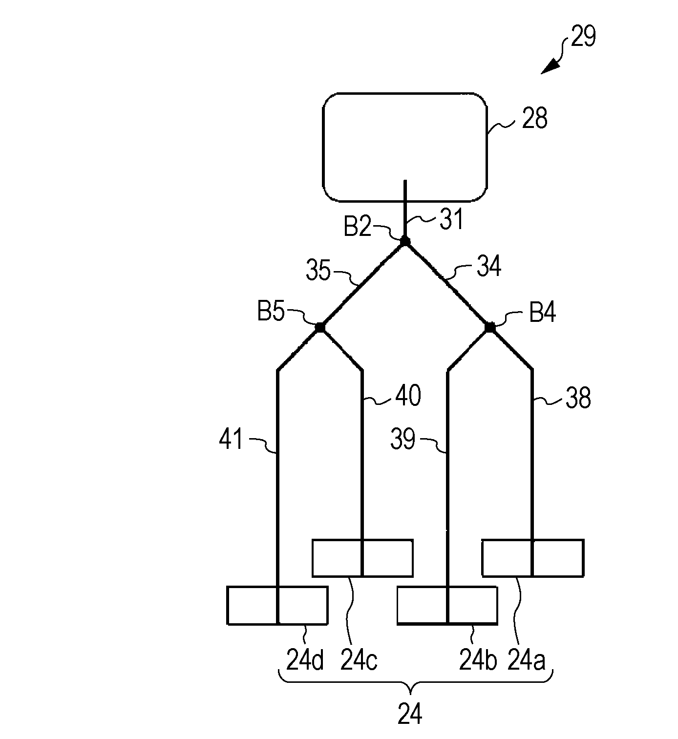
[0059]As shown in FIG. 4A, the downstream end of the main flow path 31 may be connected to the branch point B2 in the ink supplying flow path 29 so as to provide the four recording heads 24.

[0060]As shown in FIG. 4B, the downstream end of the main flow path 31 may be connected to the branch point B4 in the ink supplying flow path 29 so as to provide the two recording heads 24. In other words, only one branch point may be provided in the ink supplying flow path 29.

[0061]The ink supplying flow path 29 may be structured in such a manner that a flow path branches into three or more branched flow paths at each of the branch points B1 to B7. In other words, the numbers of branched flow paths at the branch points B1 to B7 in the ink supplying flow path 29 may be odd numbers of three or more or even numbers of four or more.

[0062]The numbers of branched flow paths at the branch points B1 to B7 in the ink supplying flow path 29 m...


PUM


Abstract

A liquid ejecting apparatus includes, a plurality of liquid ejecting sections ejecting liquid, and a liquid supplying flow path. In the device, an upstream side of the liquid supplying flow path is coupled to the liquid supplying source while a downstream side of the liquid supplying flow path branches into a plurality of flow paths at a branch point and each of the plurality of flow paths is coupled to one of the liquid ejecting sections. In the liquid supplying flow path, an average flow path resistance value of a flow path upstream of the branch point serving as a reference is smaller than an average flow path resistance value of a flow path having the smallest average flow path resistance value among average flow path resistance values of flow paths downstream of the branch point serving as the reference.

Description

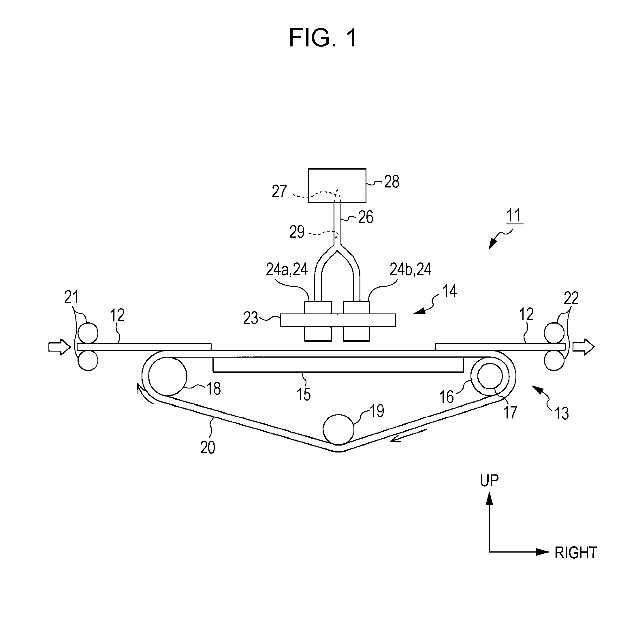
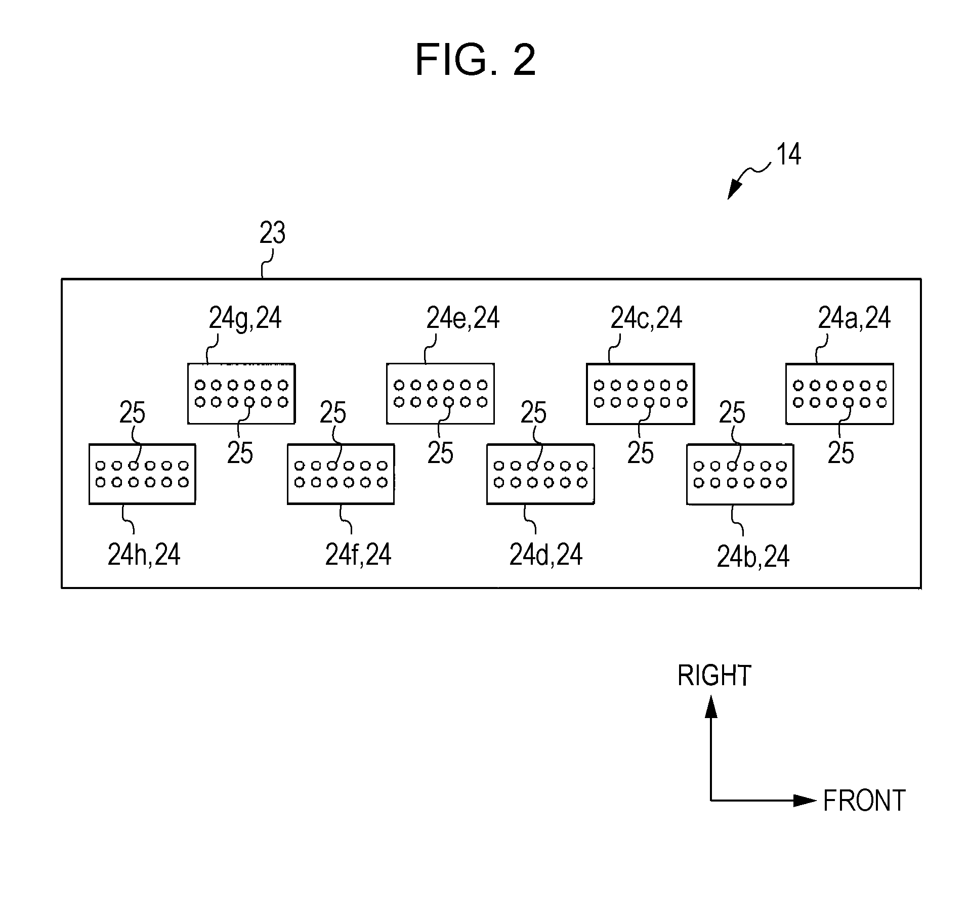
BACKGROUND[0001]1. Technical Field[0002]The present invention relates to a liquid ejecting apparatus such as an ink jet printer.[0003]2. Related Art[0004]In general, ink jet printers are widely known as a liquid ejecting apparatus that ejects liquid from a liquid ejecting head. An example of such ink jet printers is a so-called line head printer. The line head printer has a plurality of recording heads (liquid ejecting sections) that are arranged and fixed in a zigzag pattern along a width direction of a recording sheet to be transported. In printing, each nozzle of the recording heads ejects ink (liquid) to the recording sheet being transported.[0005]In such ink jet printers, the recording heads are cleaned in a timely manner so as to prevent the occurrence of ink ejection failures such as nozzle clogging and missing dots. In the cleaning process of the recording head, a cap abuts the recording head so as to surround the nozzles of the recording head, thereafter air inside a hermet...

Claims


Application Information

Patent Timeline
IPC IPC(8): B41J2/175
CPCB41J2/175
Inventor KOBASHI, MASARU
Owner SEIKO EPSON CORP
Learn More