Image combining apparatus and method for aligning positions of images

Inactive Publication Date: 2011-08-18
KONICA MINOLTA BUSINESS TECH INC
View PDF1 Cites 10 Cited by
  • Summary
  • Abstract
  • Description
  • Claims
  • Application Information

AI Technical Summary

Benefits of technology

[0023]According to the image combining apparatus and the image positioning method of the present invention, the relationship between the position of projected image on the view

Problems solved by technology

However, according to this method, an image to show the standard position is projected from the image projection apparatus, so that a certain mark is projected onto the viewing surface, whereby pictorial figures, being similar to said certain mark, such as a round mark, cannot be used on the board, and if no mark has been applied, the image data cannot be combined, which are adverse matters.
Further, concer

Method used


Image

  • Image combining apparatus and method for aligning positions of images
  • Image combining apparatus and method for aligning positions of images
  • Image combining apparatus and method for aligning positions of images

Examples


embodiments

[0050]In order to more fully detail the embodiment of the present invention, the positional alignment method of the image combining apparatus, and the positional alignment method of the images, relating to the embodiment of the present invention, will now be explained, while referring to FIGS. 1-20.

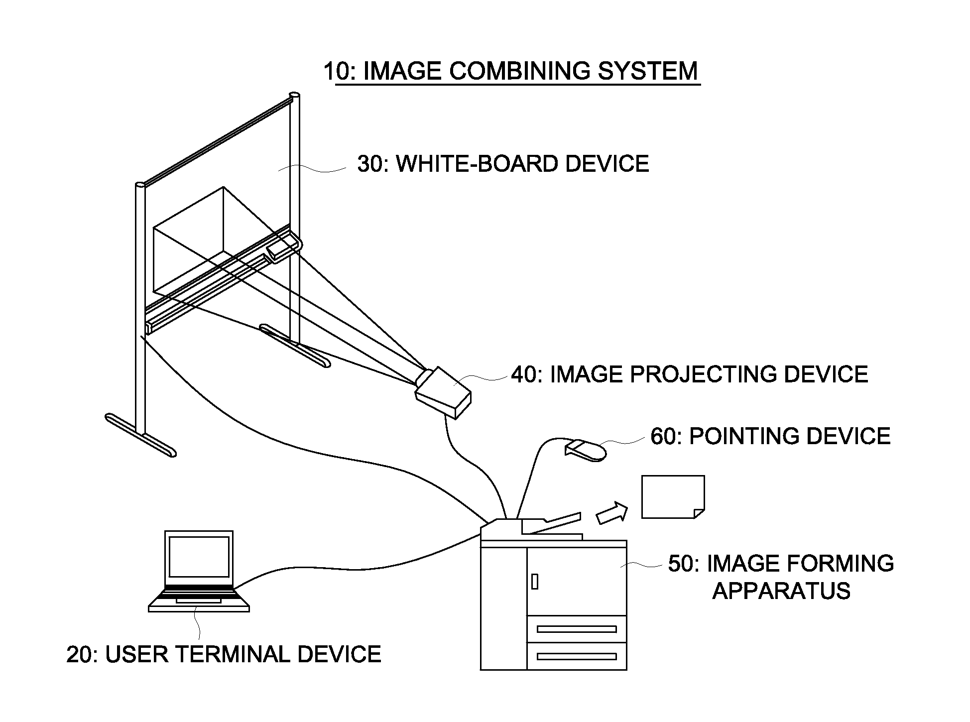
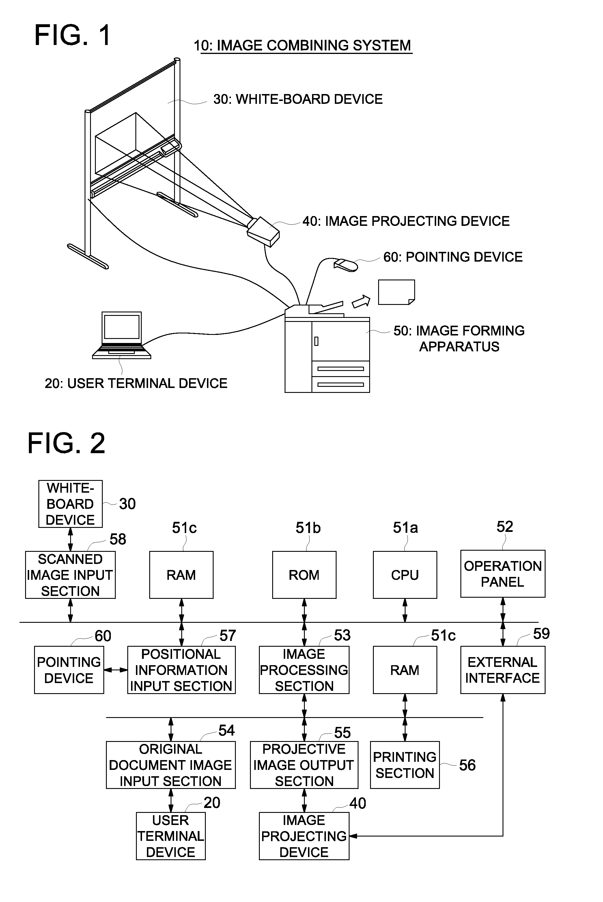
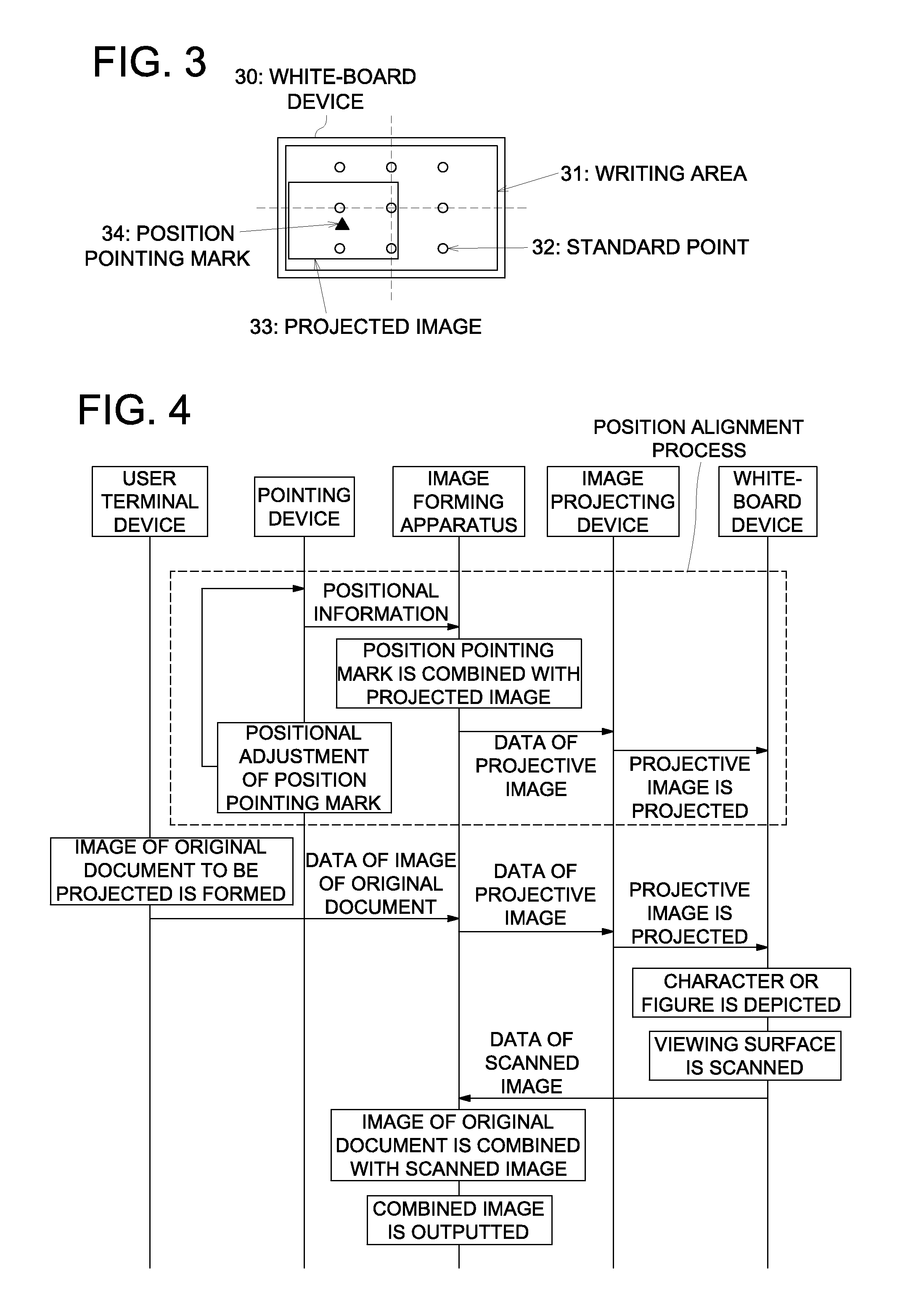
[0051]FIG. 1 shows a schematic structure of the image combining system relating to the embodiment of the present invention, FIG. 2 is a block diagram of the image forming apparatus, FIG. 3 shows the positional relationship between the projected image and the viewing surface of the white-board device, FIG. 4 is a sequence chart to show the total operation of the image combination, FIG. 5 is a flow chart to show the operation of the image forming apparatus, FIGS. 6 and 7 show an example of aligning the position pointing mark onto a standard point, FIGS. 8 and 9 show the coordinate of the standard point, and the coordinate of the position pointing mark, and FIGS. 10-20 show variations of the...


PUM


Abstract

An image combining apparatus, which is connected with a white-board device, and an image projecting device, includes an image outputting section for outputting the projective image data to the image projecting device, an operation section for designating any position on a projected image, an image processing section for generating projective image data for displaying a mark, a memory section for memorizing the coordinate positions of two or more standard points, and an image inputting section for receiving the scanned image data from the white-board device, wherein the image processing section obtains the coordinate positions of the certain marks when the two or more standard points have been designated, the image processing section makes correspondence with the coordinate positions of the certain marks and the coordinate positions of the two or more standard points respectively, whereby the image processing position recognizes the position of the projected image on the viewing surface.

Description

CROSS REFERENCE TO RELATED APPLICATION[0001]This application is based on Japanese Patent Application No. 2010-030034 filed on Feb. 15, 2010 with the Japanese Patent Office, the entire content of which is hereby incorporated by reference.TECHNICAL FIELD[0002]The present invention relates to an image combining apparatus and a method for aligning positions of images, and in particular, to an image combining apparatus which combines data of projected image on a viewing surface, with data of scanned image being read data of the images depicted on the viewing surface, and to a method for aligning the projected image and the scanned image.BACKGROUND ART[0003]In recent years, users generally use image projecting device and white-board devices for meetings, and they write outcome of the meeting on a viewing surface of a white-board device on which an image has been displayed via an image projecting device. For such purposes, well known are products, which combine a projected image, projected...

Claims


Application Information

Patent Timeline
IPC IPC(8): G06F3/12G09G5/00
CPCG03B21/14H04N1/3871G03B21/26G03B21/132G03B21/56G03B21/10
Inventor KATSUDA, TAKEO
Owner KONICA MINOLTA BUSINESS TECH INC
Why Eureka
Try Eureka