Optical image systems

a technology of optical image and image, applied in the field of optical image systems, can solve problems such as increased degradation, worsening of problems, and inability to solve parallax problems

Inactive Publication Date: 2011-08-18
SRI INTERNATIONAL
View PDF2 Cites 103 Cited by
  • Summary
  • Abstract
  • Description
  • Claims
  • Application Information

AI Technical Summary

Problems solved by technology

This degradation is heightened by a large depth of field and near camera imagery.
Specifically, when objects are within a certain fixed range of a binocular color and IR camera, the parallax problem cannot be solved.
In fact, this probl...

Method used


Image

  • Optical image systems
  • Optical image systems
  • Optical image systems

Examples


Embodiment Construction

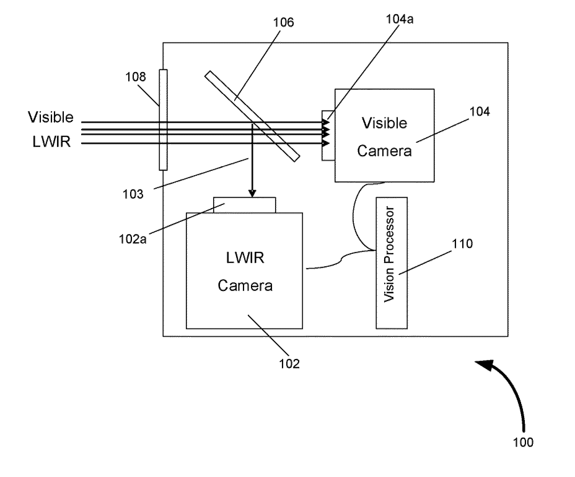
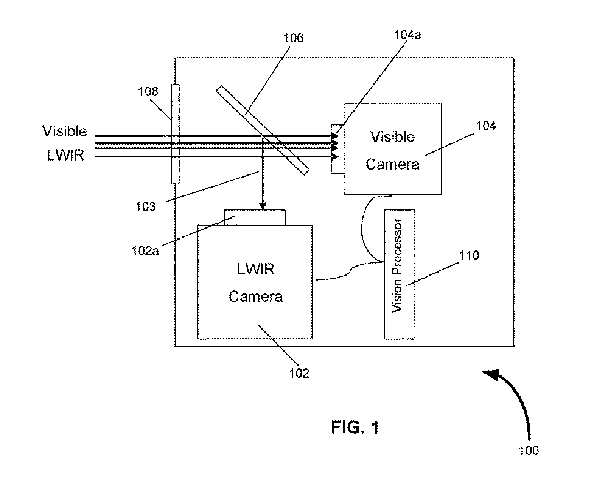
[0015]The present invention solves the problem of parallax by an application of a beam splitter which splits an incoming beam of electromagnetic radiation by transmitting or reflecting the beam depending on the waveband. Individual sensors commonly known as cameras are sensitive to each split beam receive the split beam and if equipped with a zoom lens they adjust their zoom for magnification. A processor controls all the camera zooms such that the image size in all cameras are equal at all levels of zoom. The placement of the lens behind the beam splitter allows the use of a wide variety of narrow chromatic band lenses that are chromatically optimized for each camera. This flexibility in lens selection enables a design with a wider range of environmental robustness. It also allows for a larger range of material choices for use in the lens system. This expansion of material choice enables the creation of a parallax free fused camera systems that can span a much larger section of the...


PUM


Abstract

The present invention is an optical image system having at least a first camera including a first lens and at least a second sensor including a second lens. The system also includes at least one beam splitter for transmitting an incoming beam of electromagnetic radiation of at least a first band of wavelength to a focal plane array of the first camera and reflecting an incoming beam of electromagnetic radiation of at least a second band of wavelength to a focal plane array of the second camera. The first lens is positioned behind the beam splitter for focusing the beam of the first band of wavelength onto an image at the focal plane array of the first camera and the second lens is positioned behind the beam splitter for focusing the beam of the second band of wavelength onto the image at the focal plane array of the second camera.

Description

CROSS-REFERENCE TO RELATED APPLICATIONS[0001]This application claims the benefit of U.S. Provisional Patent Application No. 61 / 303,818, filed Feb. 12, 2010, titled, “Parallax-Free Optical System / Camera” and also claims the benefit of U.S. Provisional Patent Application No. 61 / 320,798 filed Apr. 5, 2010, titled, “Parallax-Free Optical System / Camera”, both of which is herein incorporated by reference.FIELD OF THE INVENTION[0002]The invention relates generally to optical systems. More specifically, the invention relates to an improved optical image system for fusing images of various wavelengths while eliminating parallax effects and chromatic abberation.BACKGROUND OF THE INVENTION[0003]Fused imagery of multiple different sets of wavelengths of light such as Infrared, visible etc. is distorted, non-uniformly, focused, missaligned and rendered useless by excessive parallax. This degradation is heightened by a large depth of field and near camera imagery. Large depths of field images hav...

Claims


Application Information

Patent Timeline
IPC IPC(8): G03B41/00H04N9/09
CPCG03B17/02G03B19/07H04N5/2258H04N5/332H04N5/23232H04N5/33H04N5/232H04N23/45H04N23/951H04N23/60H04N23/11
Inventor KRAVITZ, ARNOLDKIM, JONGJIN GEORGEGERSHTEIN, SERGEY
Owner SRI INTERNATIONAL
Why Eureka
Try Eureka