Tire vulcanizer

a tire vulcanizer and vulcanizer technology, applied in the field of tire vulcanizers, can solve the problems of difficult adjustment and increase the overall height of the tire vulcanizer, and achieve the effects of easy adjustment, easy control, and improved accuracy of positioning the top mold mounting member

Active Publication Date: 2011-08-18
KOBE STEEL LTD
View PDF9 Cites 15 Cited by
  • Summary
  • Abstract
  • Description
  • Claims
  • Application Information

AI Technical Summary

Benefits of technology

[0024]According to the above configuration, the threaded rod is rotated in the forward and reverse directions using the motor, to thereby lift up and down the nut in the vertical direction, and, in turn, to lift up and down the top mold mounting member in the vertical direction. That is to say, because the top mold mounting member is lifted up and down by a rectilinear motion converted from a rotary motion of the motor whose rotation speed, rotation angle, or other features can be readily controlled, an accuracy of positioning the top mold mounting member can be improved as compared with a case where the top mold mounting member is lifted up and down using only the rectilinear motion caused by a cylinder or the like.
[0025]According to the tire vulcanizer of the present invention, the adjustment based on the height of the mold can be simplified, while reducing the overall height of the tire vulcanizer.

Problems solved by technology

In any of the tire vulcanizers described in the above patent publications, however, the adjustment based on the height of the mold is conducted through the use of the mold height adjusting device, etc. installed at a location vertically extended from the mold as described above, which presents a problem in that an overall height of the tire vulcanizer is increased.
The adjustment based on the height of the mold is performed depending on the amount of screwing the adjusting threaded shaft into the adjusting threaded sleeve, an amount of rotation of the nut relative to the threaded part of the spacer, etc. as explained above, which make the adjustment difficult to achieve.

Method used


Image

  • Tire vulcanizer
  • Tire vulcanizer
  • Tire vulcanizer

Examples


Embodiment Construction

[0033]With reference to drawings, an embodiment of a tire vulcanizer according to the present invention will be described below.

[Overall Structure of Tire Vulcanizer]

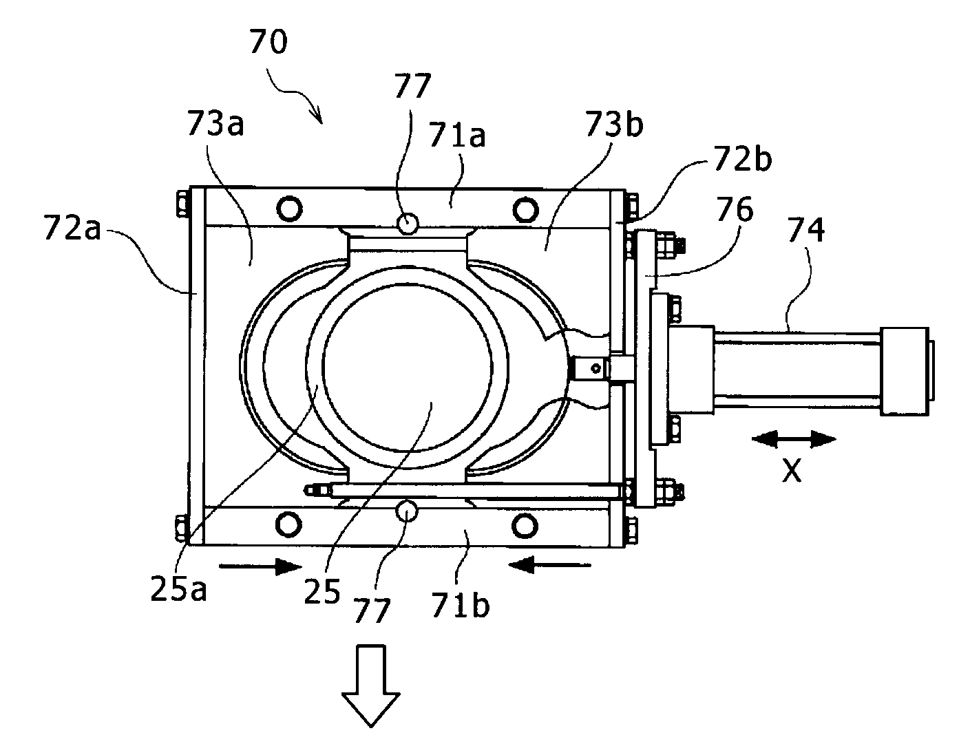
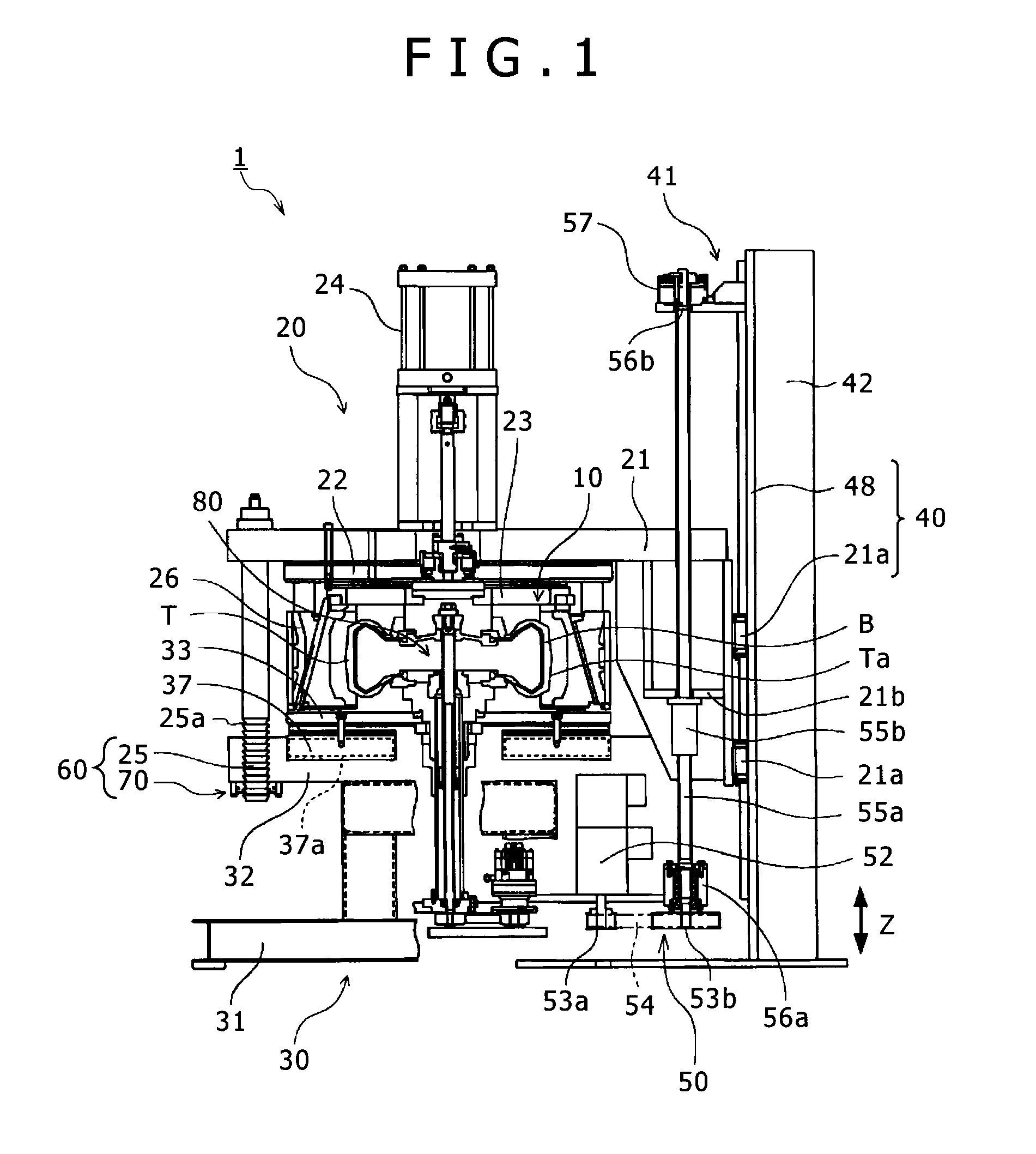
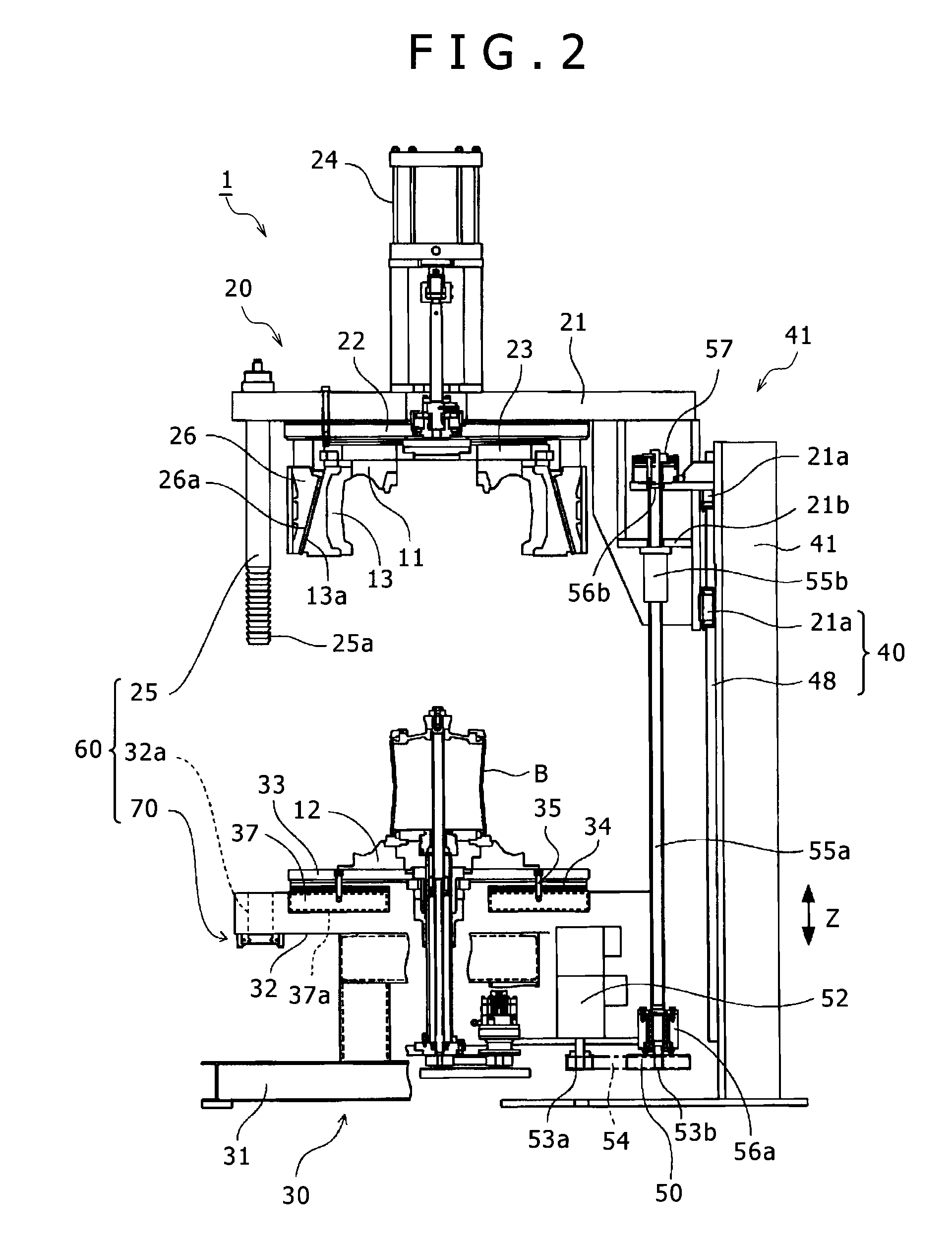
[0034]A tire vulcanizer 1 according to this embodiment is a press device of a type in which a raw tire T is heated from inside by a heating and pressurizing medium inserted in the raw tire T, and is also vulcanized by heating a mold 10 from outside. As shown in FIGS. 1 and 2, the tire vulcanizer 1 mainly comprises the mold 10 (including a top mold 11, a bottom mold 12, and a side mold 13) for removably receiving the raw tire T, a top mold mounting member 20 for retaining the top mold 11, a bottom mold mounting member 30 for retaining the bottom mold 12, a guiding mechanism 40 for guiding the top mold mounting member 20 along a vertical direction, an opening and closing mechanism 50 for moving up and down the top mold mounting member 20 in the vertical direction and causing the top mold 11 and bottom mold 12 to be opened...


PUM

PropertyMeasurementUnit
clamping forceaaaaaaaaaa
vertical lengthaaaaaaaaaa
lengthaaaaaaaaaa

Abstract

In a tire vulcanizer of the present invention, a locking mechanism which secures a top mold and a bottom mold in a closed condition comprises tie rods disposed alongside the top mold, and each having a top end part fixed to a top mold mounting member and a lower end part on which a plurality of grooves are formed one above the other in a vertical direction; through holes formed in a bottom mold mounting member for allowing each of the tie rod to pass through each of the through holes; lock plates capable of engaging and disengaging, along a horizontal direction, with the groove on each tie rod having passed through each through hole, and lock plate shifting mechanisms each opening and closing the lock plates only in a horizontal direction relative to each tie rod. With the configuration as described above, adjustment based on a height of a mold is simplified, while reducing an overall height of the tire vulcanizer.

Description

BACKGROUND OF THE INVENTION[0001]1. Field of the Invention[0002]The present invention relates to a tire vulcanizer. More particularly, the present invention relates to a tire vulcanizer in which a distance between top and bottom mold mounting members can be adjusted based on a height of a mold.[0003]2. Description of the Related Art[0004]A tire vulcanizer is a machine in which an unvulcanized raw tire (a green tire) received in a mold is vulcanized and patterned by applying heat from both inside and outside the mold. In general, a mold of the tire vulcanizer comprises a two-part mold which is divided into two, top and bottom, parts. A top mold and a bottom mold of the two-part mold are respectively retained by a top mold mounting member and a bottom mold mounting member. Then, opening and closing of the mold can be achieved by moving up and down the top mold mounting member along a vertical direction relative to the bottom mold mounting member.[0005]Here, when the mold is replaced i...

Claims


Application Information

Patent Timeline
Patent Type & Authority Applications(United States)
IPC IPC(8): B29C35/00
CPCB29D30/0601B29C33/202
Inventor FUJIEDA, YASUHIKOSHIBATA, MASAHARU
Owner KOBE STEEL LTD
Why Eureka
Try Eureka