Wireless Tracking System And Method Utilizing Near-Field Communication Devices

Inactive Publication Date: 2011-08-18
AWAREPOINT CORPORATION
View PDF5 Cites 32 Cited by
  • Summary
  • Abstract
  • Description
  • Claims
  • Application Information

AI Technical Summary

Benefits of technology

[0034]Each communication device preferably has a low-power, short-range (<1 foot) communication feature that can detect the presence, or absence, of a signal from another device. Short bits of information are preferably exchanged (<256 bits) between devices but such an exchange is not mandatory. RFID systems operating at frequencies of sub-125 kHz, 125 kHz, 433 MHz, 900 MHz, or 2.4 GHz are used with the present invention. The communication devices alternatively transmit at frequencies as low as 5 kiloHertz (“kHz”) and as high as 900 MegaHertz (“MHz”). Other frequencies utilized by the tags for a low-power short-range communication system include 9 kHz, <125 kHz, 433 MHz, and 900 MHz.
[0035]Each device preferably contains a low-power, medium-range (1 foot to 30 feet) wireless communication system. Such wireless communication systems include ZIGBEE, BLUETOOTH, Low-Power BLUETOOTH, WiFi or Low-Power WiFi, Ultra Wide Band (“UWB”), Ultrasound and Infrared communication systems. The wireless communication system is used to exchange device specific information after the low-power short-range system has indicated that an interaction has occurred. Those skilled in the pertinent art will recognize that the wireless communication system can also be used independent of the low-power short-range system for other wireless communication

Problems solved by technology

As stated above, the problem is inadequate resource visibility in a business.
Specific problems for hospitals include tracking infections in a hospital to determine a source and other areas or individual

Method used


Image

  • Wireless Tracking System And Method Utilizing Near-Field Communication Devices
  • Wireless Tracking System And Method Utilizing Near-Field Communication Devices
  • Wireless Tracking System And Method Utilizing Near-Field Communication Devices

Examples


Example

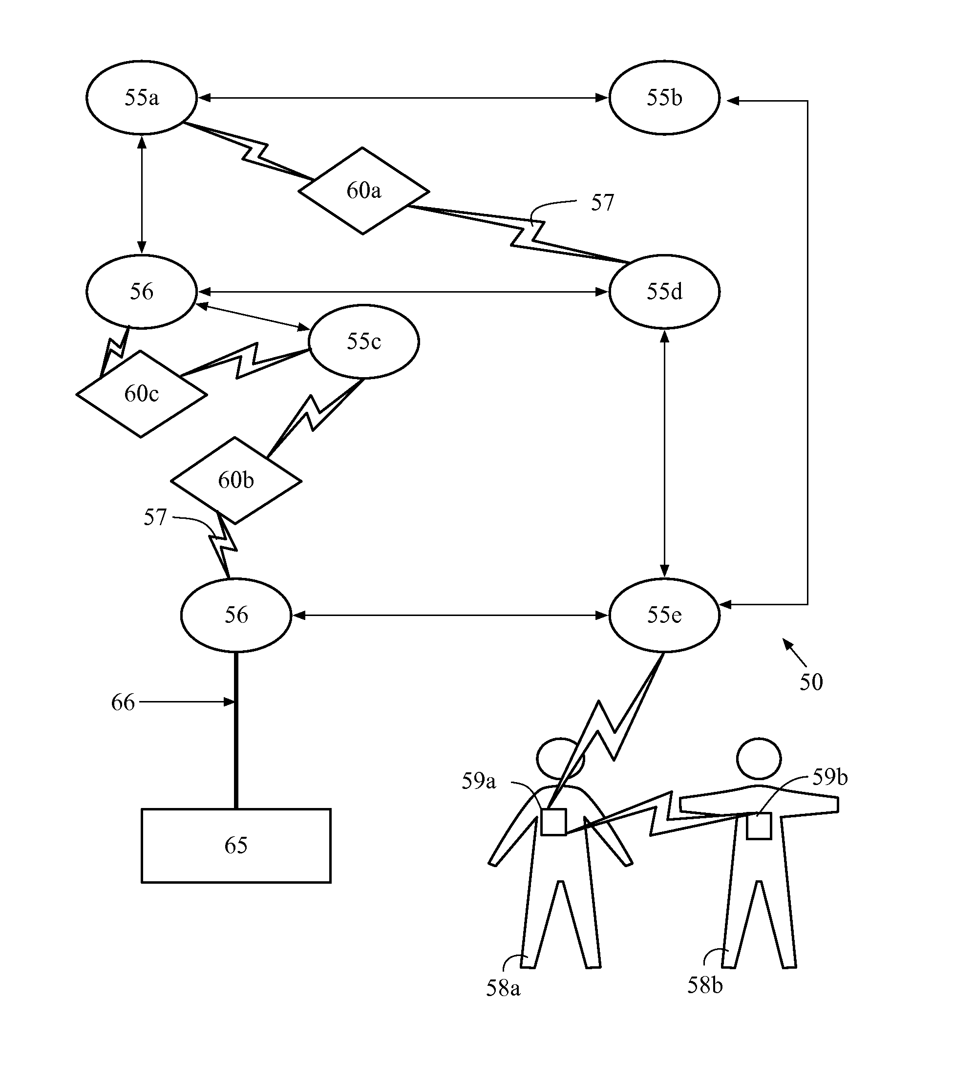
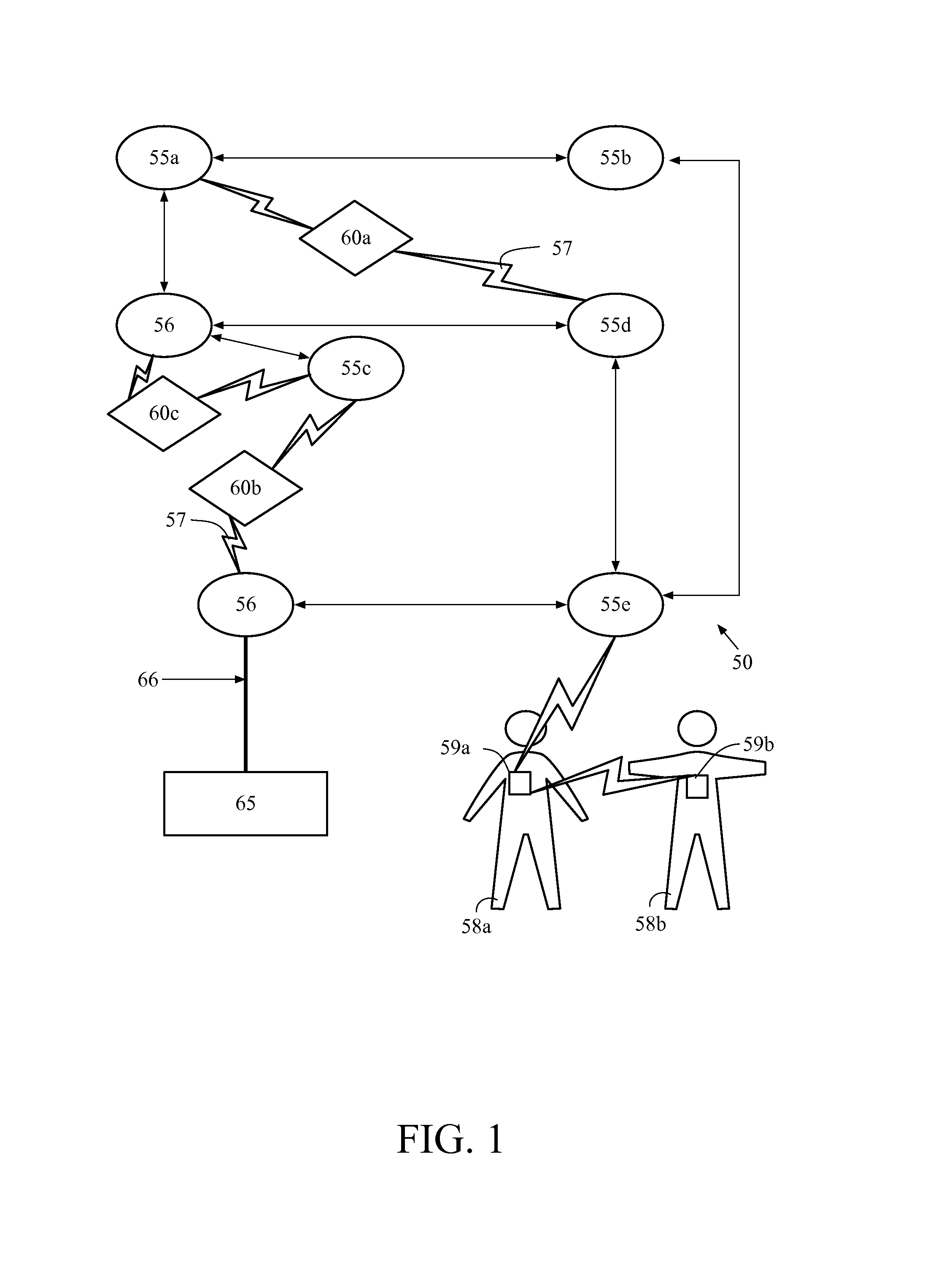
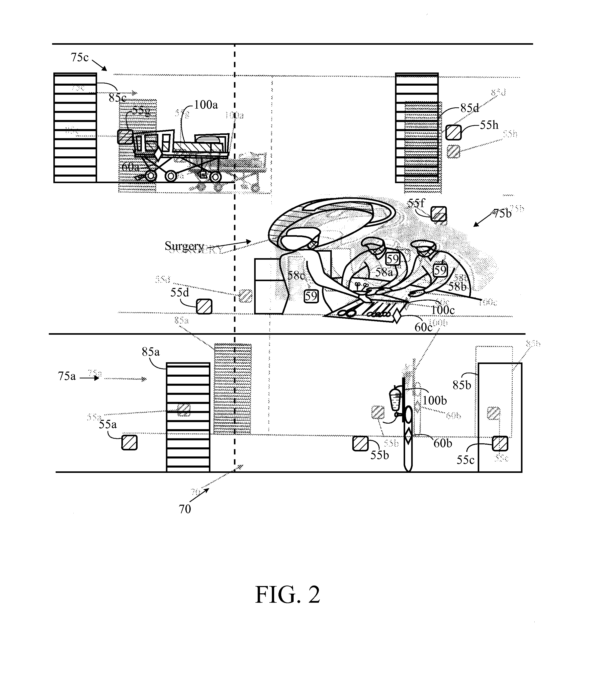
[0051]As shown in FIGS. 1-3, a system for tracking objects within a facility is generally designated 50. The system 50 is capable of analyzing an interaction between objects, individuals 58 and / or objects 100. The system 50 preferably includes a plurality of sensors 55, a plurality of bridges 56, a plurality of near-field communication devices 59, a plurality of tags 60, and at least one information engine 65. The sensors 55 form a mesh network for receiving signals from the near-field communication devices 59 and tags 60. One example of the components of the system 50 is disclosed in U.S. Pat. No. 7,197,326, for a Wireless Position Location And Tracking System, which is hereby incorporated by reference in its entirety. A more specific example of the sensors 55 is disclosed in U.S. Pat. No. 7,324,824, for a Plug-In Network Appliance, which is hereby incorporated by reference in its entirety.

[0052]The system 50 is preferably employed at a facility 70 such as a business office, factor...


PUM


Abstract

The present invention provides a solution to determining a near-field communication interaction in a wireless tracking mesh network. The present invention utilizes near-field communication devices in conjunction with tracking tags to transmit signals for reception by sensors stationed throughout a facility which form a mesh network and forward the signals to an information engine for analysis.

Description

CROSS REFERENCES TO RELATED APPLICATIONS[0001]The present application claims priority to U.S. Provisional Patent No. 61 / 305,146, filed on Feb. 17, 2010, which is hereby incorporated by reference in its entirety.STATEMENT REGARDING FEDERALLY SPONSORED RESEARCH OR DEVELOPMENT[0002]Not ApplicableBACKGROUND OF THE INVENTION[0003]1. Field of the Invention[0004]The present invention is related to wireless tracking systems and methods utilizing near-field communication devices. More specifically, the present invention relates to a system and method utilizing near-field communication devices for analyzing near-field communication interactions.[0005]2. Description of the Related Art[0006]Real-time knowledge of resources, whether the resources are assets or people, is becoming a necessary tool of many businesses. Real-time knowledge of the location, status and movement of crucial resources can allow a business to operate more efficiently and with fewer errors. However, many businesses employ ...

Claims


Application Information

Patent Timeline
IPC IPC(8): H04B5/00H04W4/80
CPCH04W4/008G06Q10/087H04W4/80
Inventor PERKINS, MATTHEW R.TRUSCOTT, ANTHONY
Owner AWAREPOINT CORPORATION
Why Eureka
Try Eureka