Distributed antenna system for MIMO communications

a technology of distributed antennas and communications, applied in the field of wireless communication systems, can solve the problem that distributed antenna systems cannot take advantage of mimo technology

Active Publication Date: 2011-08-18
ANDREW WIRELESS SYST GMBH
View PDF92 Cites 236 Cited by
  • Summary
  • Abstract
  • Description
  • Claims
  • Application Information

AI Technical Summary

Benefits of technology

[0010]Alternative embodiments of the invention also provide a method for determining the placement of a plurality of antennas of a distributed antenna system with a computing system of the type that includes one or more processors and a memory. In those alternative embodiments, the method comprises simulating a first remote unit communicating a first signal over a first air interface located within an environment at a first loc

Problems solved by technology

Generally, distributed antenna systems cannot take advantage of MIMO technology because they are just designed to provide SISO wireless coverage.
Additional problems occur with a distributed antenna system d

Method used


Image

  • Distributed antenna system for MIMO communications
  • Distributed antenna system for MIMO communications
  • Distributed antenna system for MIMO communications

Examples


Embodiment Construction

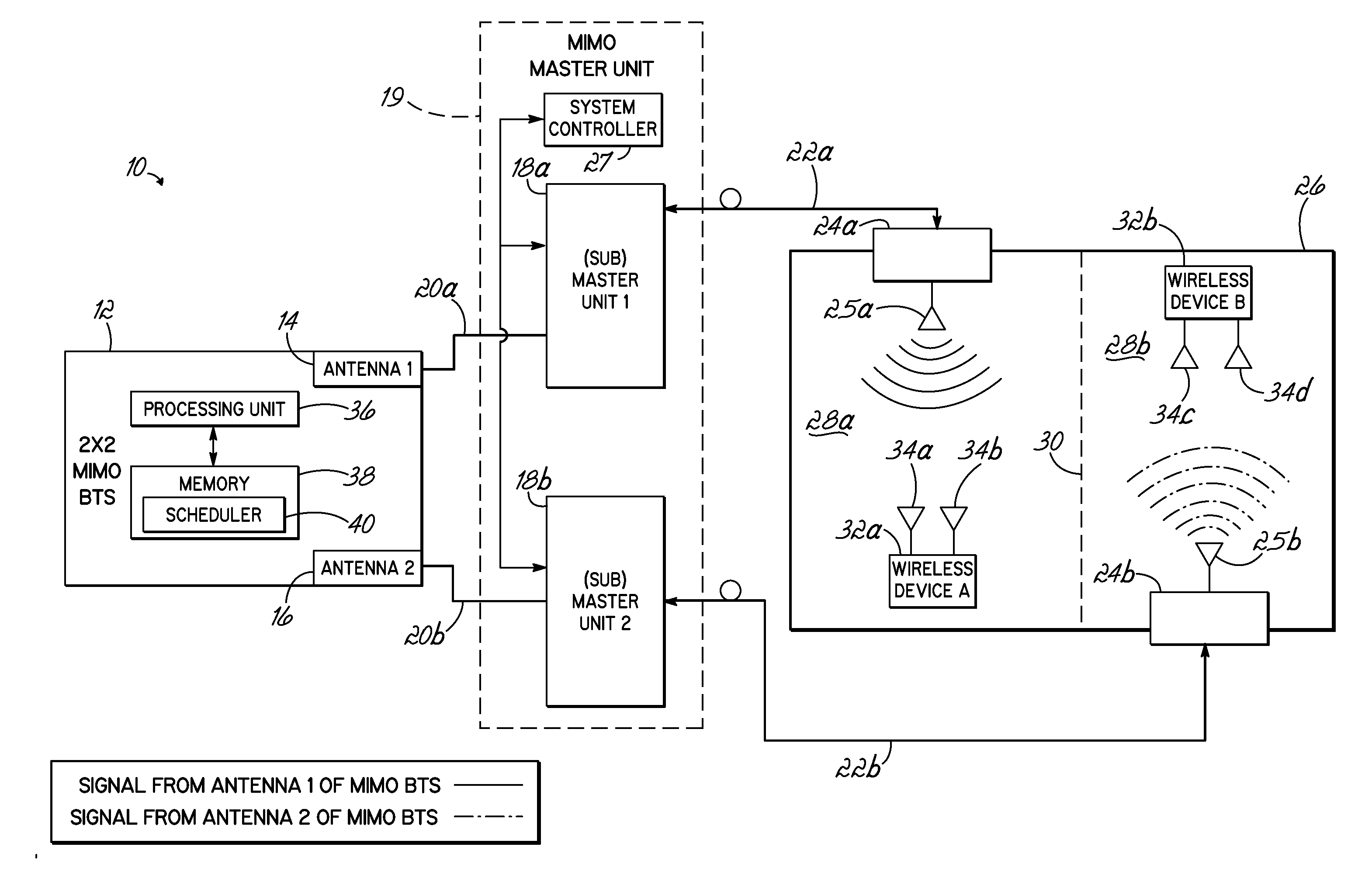
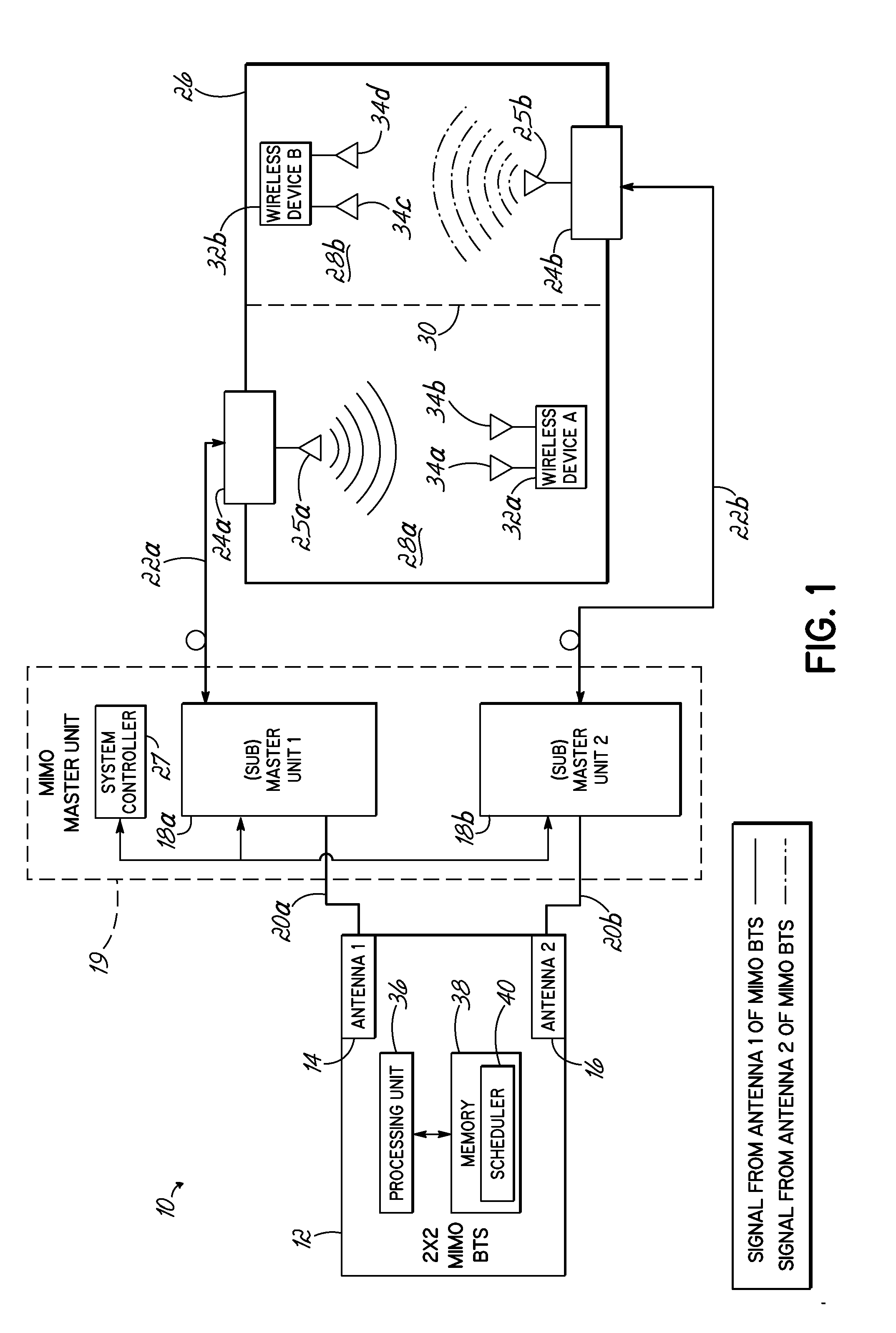
[0031]Turning to the drawings, wherein like numbers denote like parts throughout the several views, FIG. 1 illustrates a schematic view of one possible implementation of a Multiple-Input / Multiple-Output (“MIMO”) distributed antenna system 10, wherein a MIMO base station (“BTS”) 12 is incorporated in or proximate to an environment in accordance with the invention. As illustrated in FIG. 1, the system 10 includes a MIMO BTS 12 that might be configured with at least two antennas 14 and 16. While a 2×2 MIMO BTS is illustrated, one of skill in the art would understand that additional antennas might be used for a different MIMO scheme. The first antenna 14 is coupled to a first master unit 18a through a first signal link 20a, while the second antenna 16 is coupled to a second master unit 18b through a second signal link 20b. Alternatively, the MIMO BTS 12 might not be configured with antennas. In those embodiments, the MIMO BTS 12 includes at least two antenna ports (not shown) in place o...


PUM


Abstract

A method of deploying a distributed antenna system (DAS) is provided. The method comprises outputting first and second signals from a multiple-input and multiple-output base station (MIMO BTS) and coupling a master unit to the MIMO BTS. The method further comprises coupling first and second remote units to the master unit, the first remote unit communicating the first signal over a first air interface located within the environment at a first location, the second remote unit communicating the second signal over a second air interface within the environment at a second location. The first and second remote units are arranged at the first and second locations within the environment and configured to provide signal coverage of both the first signal and the second signal at a third location in the environment to provide the capacity for MIMO communications through the system at the third location.

Description

RELATED APPLICATIONS[0001]This Application claims priority to Italian Application No. BO2010A000077 filed Feb. 12, 2010, entitled “DISTRIBUTED ANTENNA SYSTEM FOR MIMO COMMUNICATIONS” and U.S. PCT Application No. US2011 / 023991, filed Feb. 8, 2011, entitled “DISTRIBUTED ANTENNA SYSTEM FOR MIMO COMMUNICATIONS”, which applications are both incorporated herein by reference in their entireties.FIELD OF THE INVENTION[0002]Embodiments of the invention are directed to wireless communication systems, and specifically directed to a distributed antenna system for wireless MIMO communications.BACKGROUND OF THE INVENTION[0003]A contemporary wireless communication system, such as distributed antenna system, includes a plurality of remote units distributed throughout a service area (e.g., a building) to provide coverage within the service area of the system. In particular, each remote antenna unit is typically coupled to a master unit, which, in turn, is coupled to at least one single-input-and sin...

Claims


Application Information

Patent Timeline
IPC IPC(8): H04B7/24
CPCH04B7/0413H04B7/0691H04B7/0426H04B7/10H04B7/022H04B7/026H04B7/0452H04B17/309
Inventor FACCIN, PIERTARLAZZI, LUIGI
Owner ANDREW WIRELESS SYST GMBH
Why Eureka
Try Eureka