Tampon applicator

Inactive Publication Date: 2011-08-18
ONTEX HIGIENEARTIKEL DEUT GMBH
View PDF3 Cites 27 Cited by
  • Summary
  • Abstract
  • Description
  • Claims
  • Application Information

AI Technical Summary

Benefits of technology

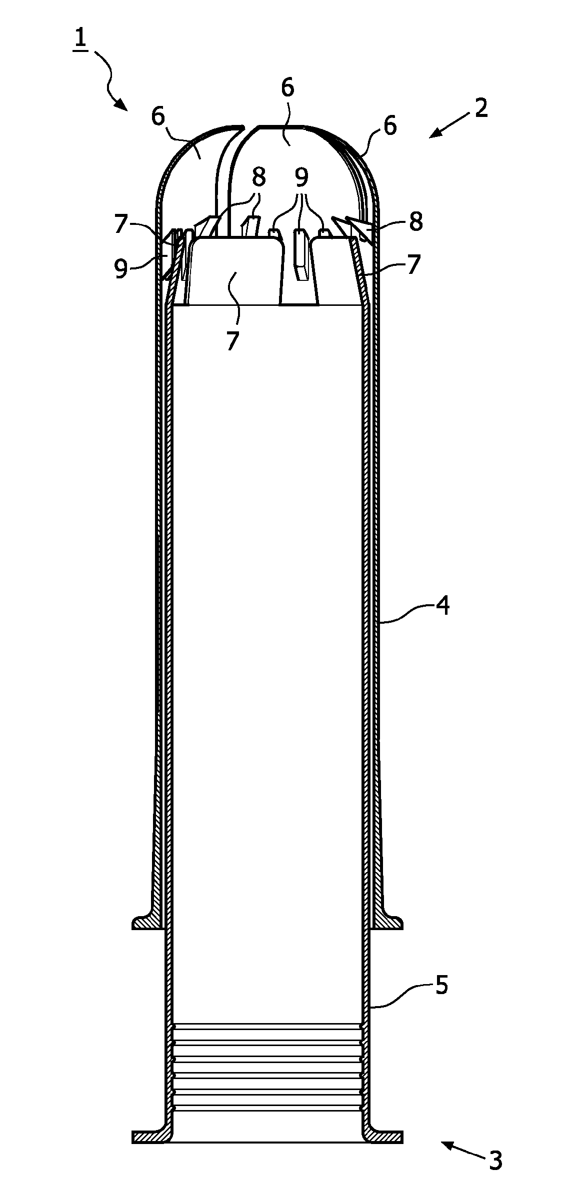
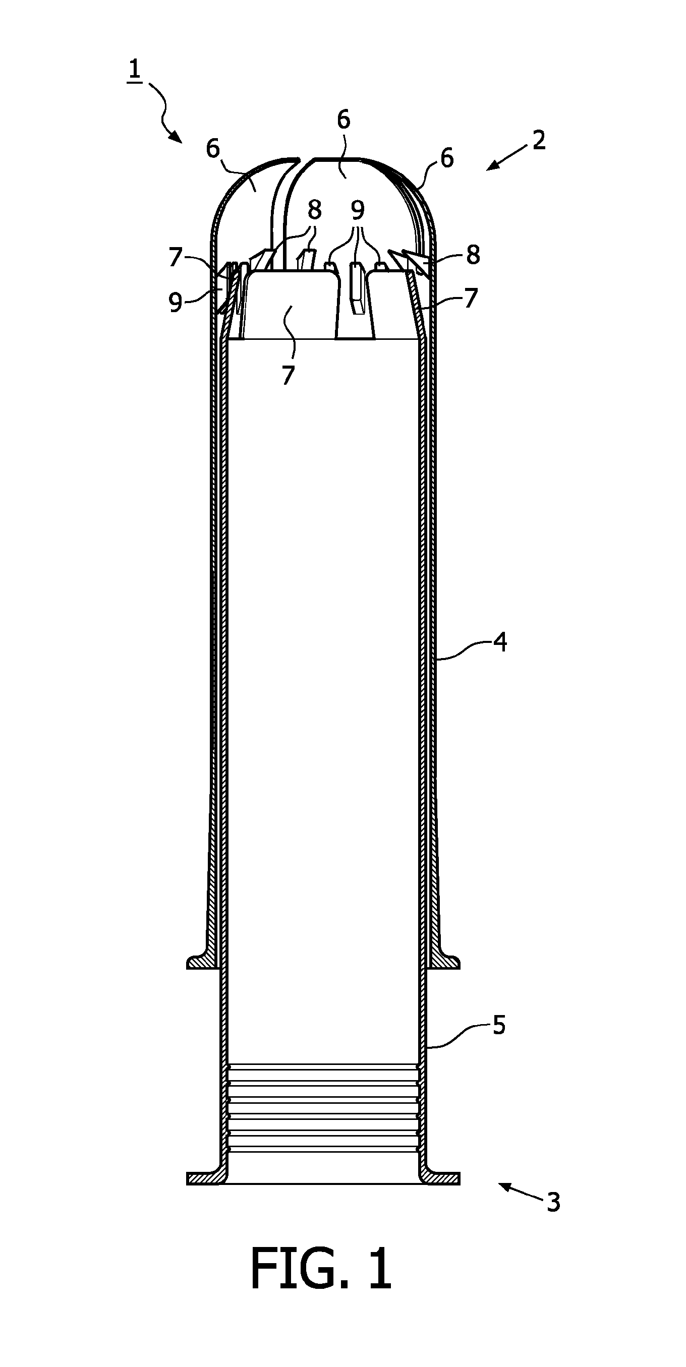
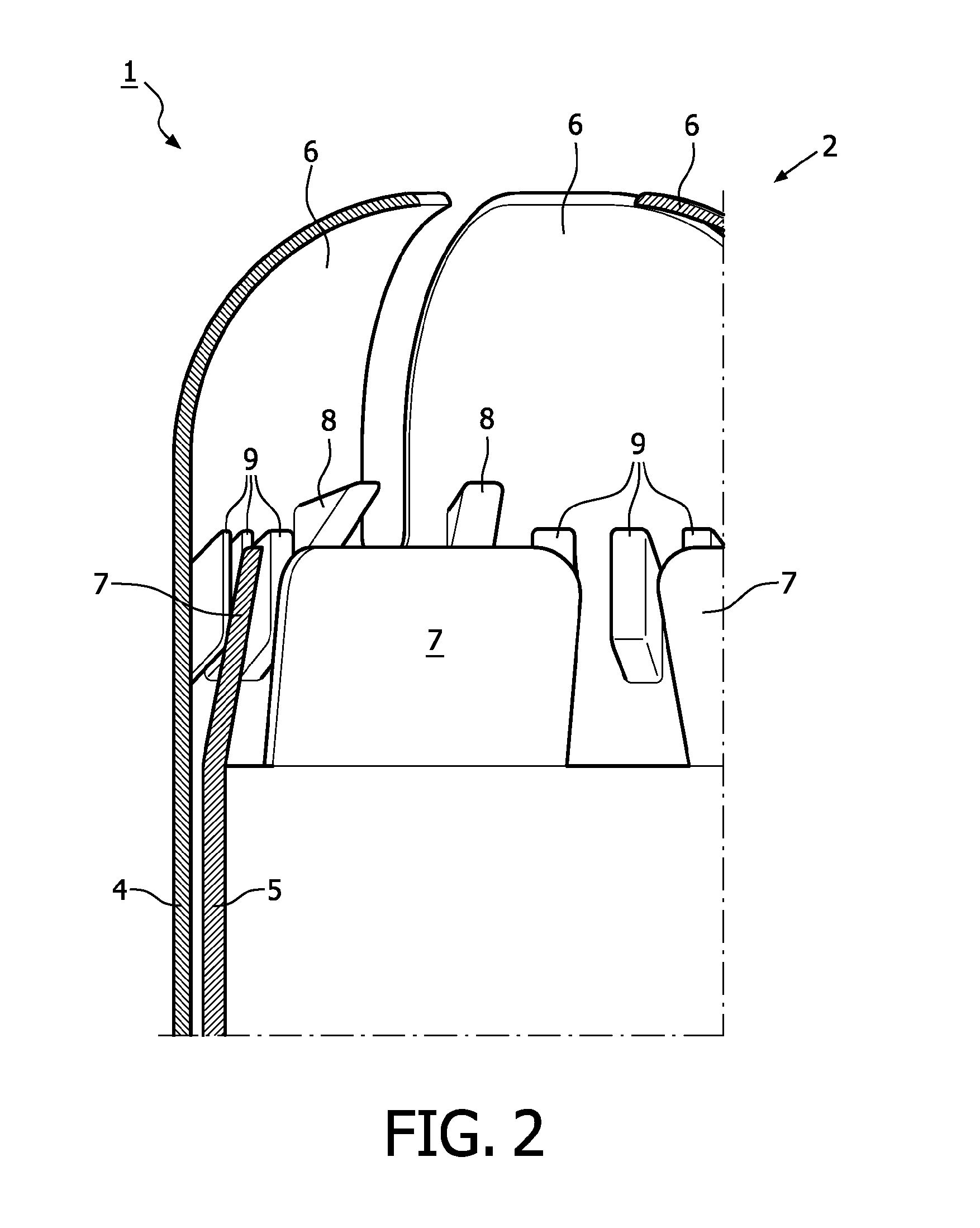
[0015]The Applicant has next surprisingly realised that if a compact tampon applicator includes tampon expansion control means configured to restrict the radially outward expansion or enlargemen

Problems solved by technology

A frequent cause of malfunction of compact tampon applicators is the re-entry of the tampon into the ejector tube when the latter is pushed back into the outer tube after the cocking step.
Clearly, in such situations, the bias of the fingers of the ejector tube towards a closed configuration has been inadequate.
Although this improves engagement of the tampon base with the fingers of the ejector tube, it also imposes additional requirements on the manufacture of the tampons and

Method used


Image

  • Tampon applicator
  • Tampon applicator
  • Tampon applicator

Examples


Embodiment Construction

[0025]As used herein, the singular forms “a”, “an”, and “the” include both singular and plural referents unless the context clearly dictates otherwise.

[0026]The terms “comprising”, “comprises” and “comprised of” as used herein are synonymous with “including”, “includes” or “containing”, “contains”, and are inclusive or open-ended and do not exclude additional, non-recited members, elements or method steps.

[0027]The recitation of numerical ranges by endpoints includes all numbers and fractions subsumed within the respective ranges, as well as the recited endpoints.

[0028]The term “about” as used herein when referring to a measurable value such as a parameter, an amount, a temporal duration, and the like, is meant to encompass variations of and from the specified value, in particular variations of + / −10% or less, preferably + / −5% or less, more preferably + / −1% or less, and still more preferably + / −0.1% or less of and from the specified value, insofar such variations are appropriate to ...


PUM

PropertyMeasurementUnit
Lengthaaaaaaaaaa
Forceaaaaaaaaaa
Expansion enthalpyaaaaaaaaaa

Abstract

A tampon applicator is described which comprises an ejector tube and an outer tube. The outer tube is dimensioned to fit closely and telescopically over the ejector tube. The outer tube has a distal discharge end. The distal end of the ejector tube is formed with one or more radially inwardly slanted fingers. The outer tube can comprise supporting means configured to restrict radially outward expansion of the fingers of the ejector tube when the tampon applicator is in telescopically compacted position.

Description

FIELD OF THE INVENTION[0001]The present invention relates to tampon applicators and is particularly directed to compact tampon applicators of the type employing telescoping tubes. More specifically, the invention concerns improvements of applicators, wherein the distal end of the ejector (or inner) tube of said applicators is formed with biased fingers.BACKGROUND OF THE INVENTION[0002]Most commercially available tampon applicators consist of a pair of telescoping tubes.[0003]In a compact tampon applicator design the ejector (or inner) tube is telescoped into the outer tube while a tampon is stored in the distal end of the ejector tube. Operatively, the ejector tube is “cocked” by being withdrawn proximally out from its stored position in the outer tube (leaving behind the tampon) until the distal end of the ejector tube is positioned to engage the proximal end of the stored tampon. Then the ejector tube can be used as a plunger and its re-insertion into the outer tube expels the tam...

Claims


Application Information

Patent Timeline
IPC IPC(8): A61F13/26B29C45/00B29C47/00
CPCA61F13/266
Inventor SMET, STEVENMATTHES, ANDREAS
Owner ONTEX HIGIENEARTIKEL DEUT GMBH
Why Eureka
Try Eureka