Method and control/regulation system for braking a vehicle, and vehicle

Inactive Publication Date: 2011-08-18
MAGNA STEYR FAHRZEUGTECHN
View PDF26 Cites 6 Cited by
  • Summary
  • Abstract
  • Description
  • Claims
  • Application Information

AI Technical Summary

Benefits of technology

[0011]In accordance with embodiments of the present invention, it is an object, therefore, to provide an enhanced method and an enhanced control/regulation system for braking a vehicle, and to provide a

Problems solved by technology

In this regard it is problematic that, although an electric drive vehicle is very well suited for the use of a regenerative braking system, as mentioned above, the vehicle is decelerated by the friction brake when the accelerator pedal is released.
Behavior of an internal combustion engine is in fact simulated, but in an unfavorable manner in terms of energy.
A pro

Method used


Image

  • Method and control/regulation system for braking a vehicle, and vehicle
  • Method and control/regulation system for braking a vehicle, and vehicle
  • Method and control/regulation system for braking a vehicle, and vehicle

Examples


Example

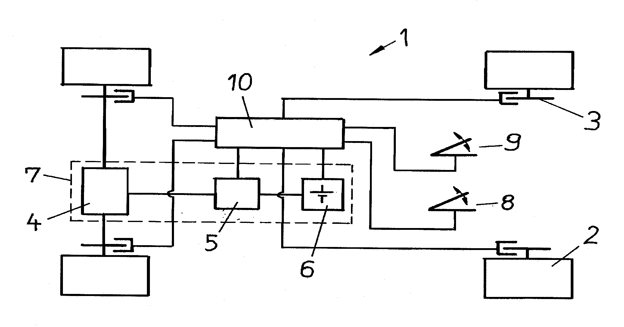
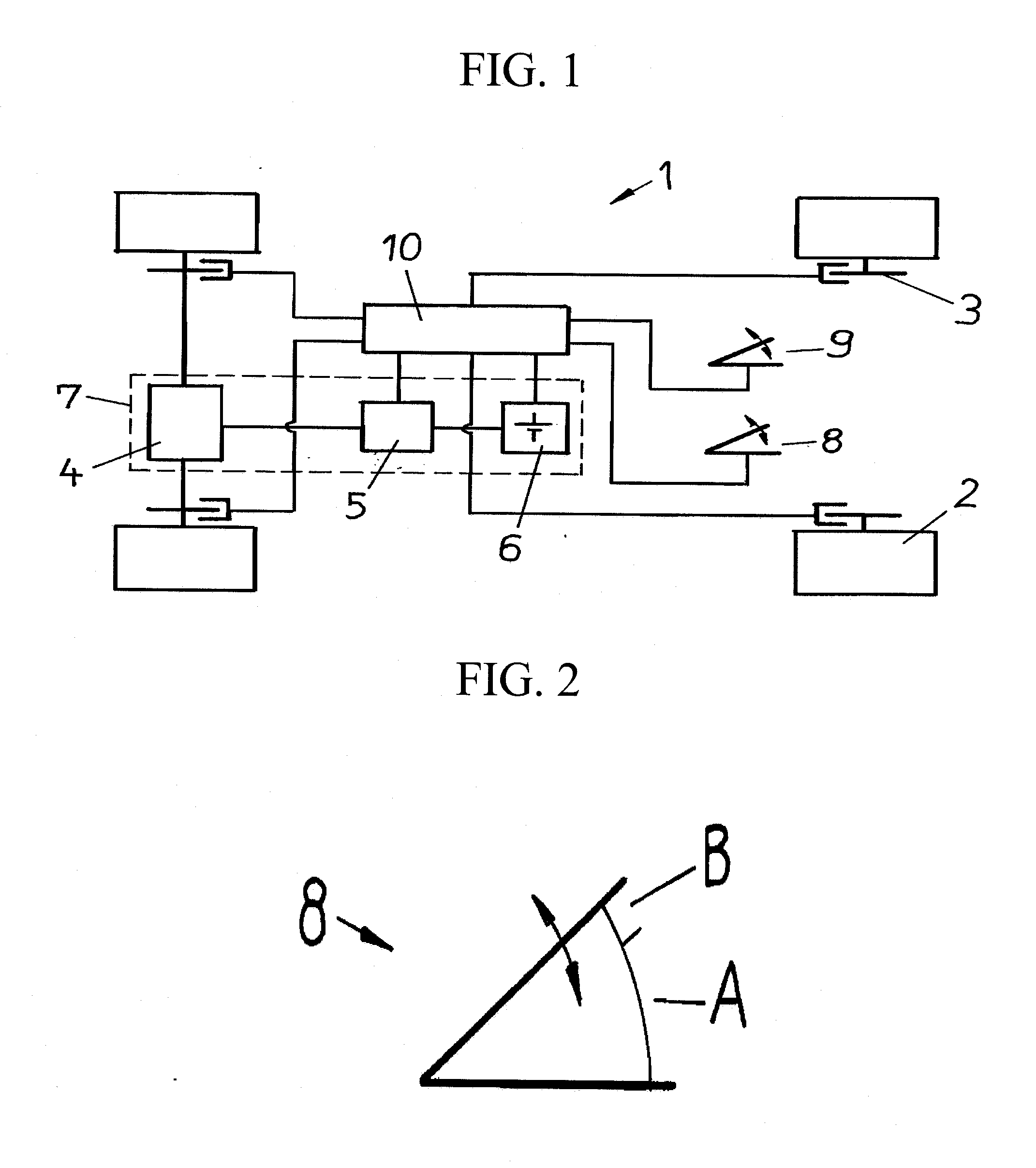
[0042]Example FIG. 1 shows an example of a schematically illustrated vehicle 1 in accordance with embodiments of the present invention. Vehicle 1 includes four wheels 2 each having friction brakes 3, and electric motor 4 for the drive of vehicle 1. Electric motor 4 is operatively connected to driving controller 5, which in turn is operatively connected to storage battery 6. Electric motor 4, driving controller 5, and storage battery 6 form regenerative braking system 7, and friction brakes 3 form the nonregenerative braking system. Vehicle 1 also includes accelerator pedal 8 and brake pedal 9. Lastly, vehicle 1 includes control / regulation system 10 which is operatively connected to regenerative braking system 7, in particular to driving controller 5 and storage battery 6. Nonregenerative braking system 3 is operatively connected to accelerator pedal 8 and brake pedal 9.

[0043]In accordance with embodiments of the present invention, vehicle 1 illustrated in example FIG. 1 functions as...


PUM


Abstract

A method and a control/regulation system for braking a vehicle having a regenerative braking system and a nonregenerative braking system, and a vehicle employing the same. The method includes detecting a position and/or a motion of an accelerator pedal and then determining whether the detected position and/or motion corresponds to a specifiable position or to a specifiable motion which is associated with a deceleration request. The regenerative braking system is correspondingly activated when the result of the check is positive. The nonregenerative braking system is additionally activated for a deceleration request which exceeds a braking capability of the regenerative braking system.

Description

CROSS-REFERENCE TO RELATED APPLICATIONS[0001]The present application claims priority under 35 U.S.C. §119 to German Patent Application No. 10 2010 027 348.1 (filed on Jul. 10, 2010) and U.S. Provisional Patent Application No. 61 / 304,883 (filed on Feb. 16, 2010), which are each hereby incorporated by reference in their respective entireties.FIELD OF THE INVENTION[0002]The invention relates to a method for braking a vehicle having a regenerative braking system and a nonregenerative braking system. In a first step a position and / or a motion of an accelerator pedal is detected. A check is then made whether the detected position and / or motion correspond(s) to a specifiable position or to a specifiable motion which is associated with a deceleration request. Lastly, the regenerative braking system is activated when the result of the check is positive.[0003]The invention further relates to a control / regulation system for a vehicle having a regenerative braking system and a nonregenerative b...

Claims


Application Information

Patent Timeline
IPC IPC(8): B60T8/17G06F19/00B60T1/10B60T7/12B60T8/171
CPCB60L7/10B60L7/24B60L2250/18B60T1/10B60T8/58B60L2200/26B60W10/08B60W10/184B60W30/18127B60W2540/10B60T2270/604
Inventor KLAUSNER, ANDREASMULLER, HELFRIEDTEUSCHL, GERALDVORRABER, WOLFGANG
Owner MAGNA STEYR FAHRZEUGTECHN
Why Eureka
Try Eureka