Apparatus and method for heating subterranean formations using fuel cells

a technology of fuel cells and apparatus, applied in the direction of fuel energy technology, insulation, borehole/well accessories, etc., can solve the problems of huge financial risks, site contamination, and huge construction costs, and achieve the effect of reducing the risk of contaminated sites and reducing the number of contaminated sites

Inactive Publication Date: 2004-02-03
IEP TECH INC
View PDF45 Cites 296 Cited by
  • Summary
  • Abstract
  • Description
  • Claims
  • Application Information

AI Technical Summary

Benefits of technology

Other heaters have been devised to eliminate flames altogether. For example, U.S. Pat. No. 5,255,742 avoids mixing of fuel and air until they reach the point of desired combustion. Problems of carbon formation are addressed by the addition of steam and / or carbon dioxide to the fuel stream as coke suppressants. In a later embodiment of the invention, U.S. Pat. No. 5,862,858, the addition of a catalyst to the combustor is intended to remove the need for coke suppression. Such flameless combustors apply heat to the ground evenly and can be adapted to formations of considerable thickness and depth.
The present invention combines the advantages of down-hole combustion heaters with the advantages of electrical resistance heaters, while eliminating most of the disadvantages typical of subterranean heaters of the prior art. The present invention converts fuel to heat, like combustion heaters, avoiding the inefficiencies of electrical resistance heaters. The present invention produces heat uniformly over the length of the heater, like electrical resistance heaters, while avoiding the hot spots and uneven heating of combustion heaters. The present invention also eliminates the problems associated with mixing fuel and air in flameless combustor heaters by maintaining separation of these gases across the fuel cell electrolyte.

Problems solved by technology

There are thousands of sites that have been contaminated by pollutants that can be driven out of the soil or decomposed in place by the application of heat.
Building such enormous facilities means taking huge financial risks before the first dollar of revenue can be realized.
This fact, together with the environmental complications of such projects, has prevented their being brought to fruition in the past.
All of the previously proposed in-situ methods for applying subterranean heat have suffered from serious disadvantages.
For example, those that require inputs of electrical energy, like electrical resistance heaters and microwave electrodes, face serious thermodynamic and economic inefficiencies.
According to U.S. Pat. No. 5,297,626: "The high cost of electrical energy is also an impediment to commercial projects using these prior art methods.
Conversion of hydrocarbons to electrical energy is typically accomplished at only about 35 percent efficiency and requires a considerable capital investment."
The Ljungstrom Method was used briefly in Sweden only because that country had an abundance of cheap hydropower and an acute shortage of liquid transportation fuels.
Other electrically powered systems for ground heating are reportedly less demanding of electricity than the Ljungstrom Method, but are still uneconomic.
These systems avoid the intermediate step of producing electricity and therefore are thermodynamically superior, but still suffer from economic shortcomings that have thus far prevented their widespread adoption.
Aside from the obvious difficulties and doubtful economics of using nuclear power to produce oil, this process also required that heat be imparted to the ground through the circulation of a hot working fluid through a heat exchanger.
While such heat circulating systems avoid the inefficiencies of electrical heaters, they nevertheless have considerable problems of their own.
One such problem is that the working fluids are necessarily hotter at the top of the formation than at the bottom and therefore do not heat the formation uniformly.
Such systems also require large mass flows and correspondingly incur large costs associated with pressurizing and pumping large volumes of fluids.
The net result is that, other considerations aside, such systems are probably not feasible except for resources in relatively thin deposits.
According to U.S. Pat. No. 6,056,057: "Injection of heat using only combustion gases to depths of greater than about 200 to 400 feet may be relatively expensive."
This results in uneven heating of the formation with poor results.
Open flames, which can produce local temperatures of 1650 degrees C., also create uneven stresses and thermal erosion within the burners.
These hot spots lead either to limited equipment life or to high expenses for exotic materials.
One problem common to such elongated burners involves the mixing of fuel and air.
If the air and fuel are mixed on the surface, there is a very real danger of auto-combustion when the temperature of the mixture rises above a critical point on its way to the burner.
This problem limits the use of such elongated burners to thin formations under shallow overburden.
One of the main problems with combustion heaters of all types is that they must consume an outside source of fuel.
Purchase of this fuel amounts to a significant expense.
Operating the heater for two years would incur expenses in excess of $27,000.
When the fuel cost per heater is multiplied by the large number of heaters required, it can be seen that this is a substantial front-end expense--$270 million per square mile--and can represent a significant fraction of overall project costs.
Even after production of combustible gases has been established from a hydrocarbon formation, the cost of fuel for combustion heaters is still significant.
This gas can be sent back down the bore holes to fire the burners, but it cannot be taken as "free".
The high cost of fueling combustion heaters is one of the reasons that this particular method of in-situ resource extraction has not yet achieved widespread adoption.

Method used


Image

  • Apparatus and method for heating subterranean formations using fuel cells
  • Apparatus and method for heating subterranean formations using fuel cells
  • Apparatus and method for heating subterranean formations using fuel cells

Examples


third embodiment

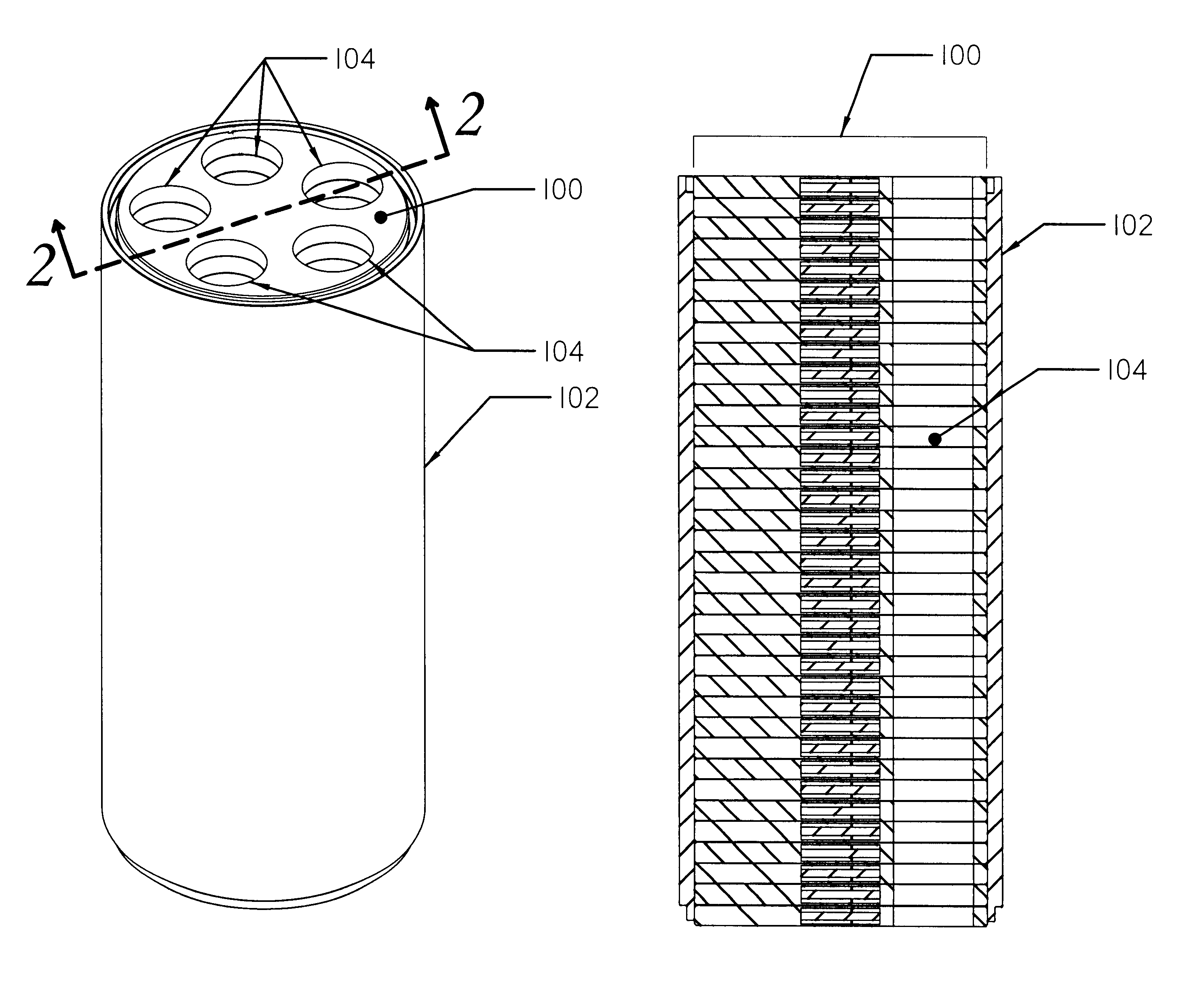
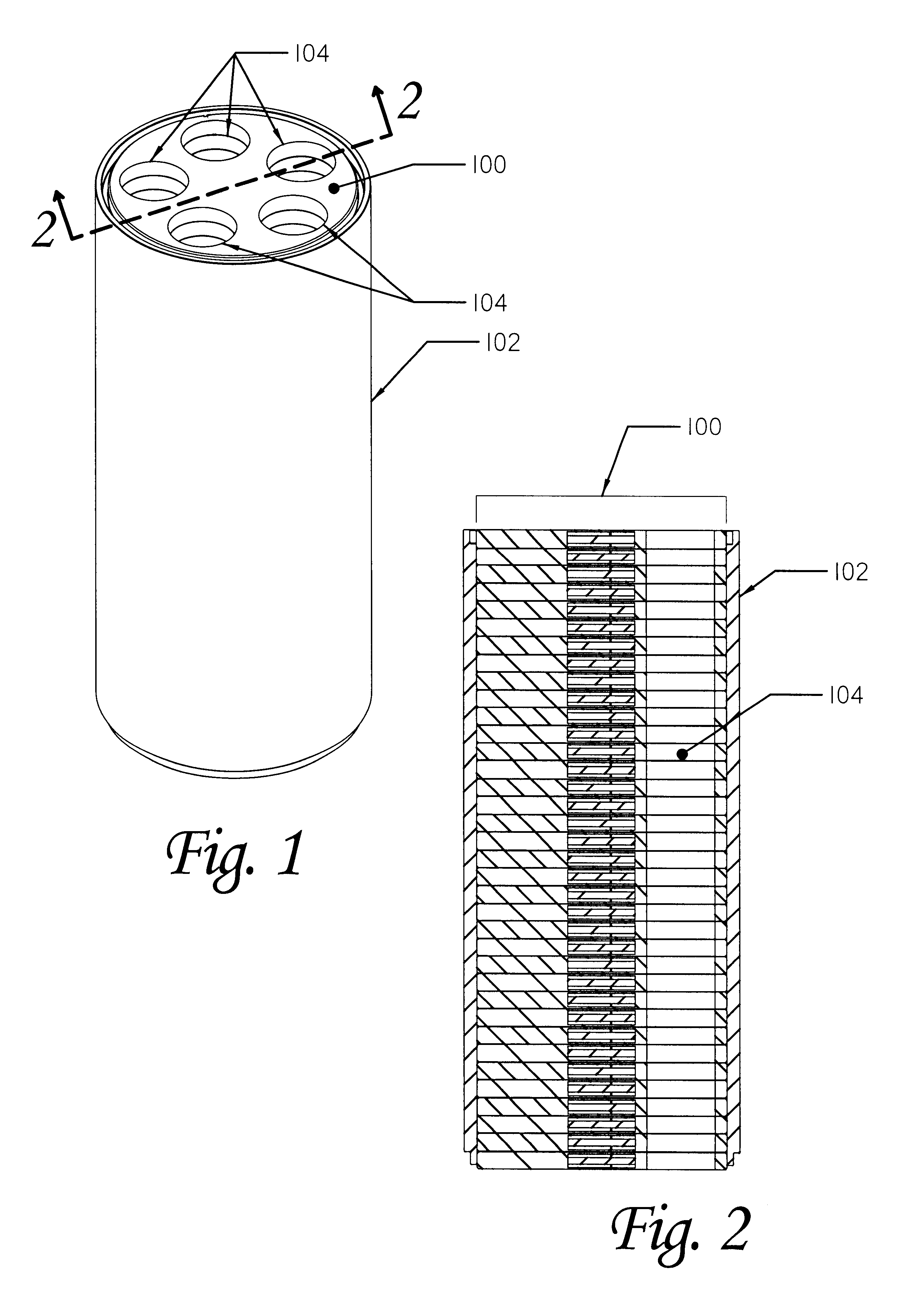
The above embodiments offer an advantage over the third embodiment discussed below in that they provide substantially more internal volume within the fuel cell stack for the movement of fuel, air, and exhaust gases through the stack, the height of which may be 500 feet or more. For example, each fuel conduit running the full length of the stack could have a diameter of two inches. The gas flow rate might typically be 777 cubic feet per hour to supply the stack with sufficient fuel. Such a conduit would allow the gas, at standard atmospheric pressure, to flow at an average speed of 589 feet per minute, or around 7 miles per hour. If the pressure is increased in the fuel conduit, the flow rate can be reduced further. The various plates may be made of ceramic, metal, composites, or other materials. Primary considerations include resistance to corrosion or other reaction with the fuel, air, and exhaust gases; conductivity; thermal expansion; and strength.

Referring again to FIGS. 1 and 2...

first embodiment

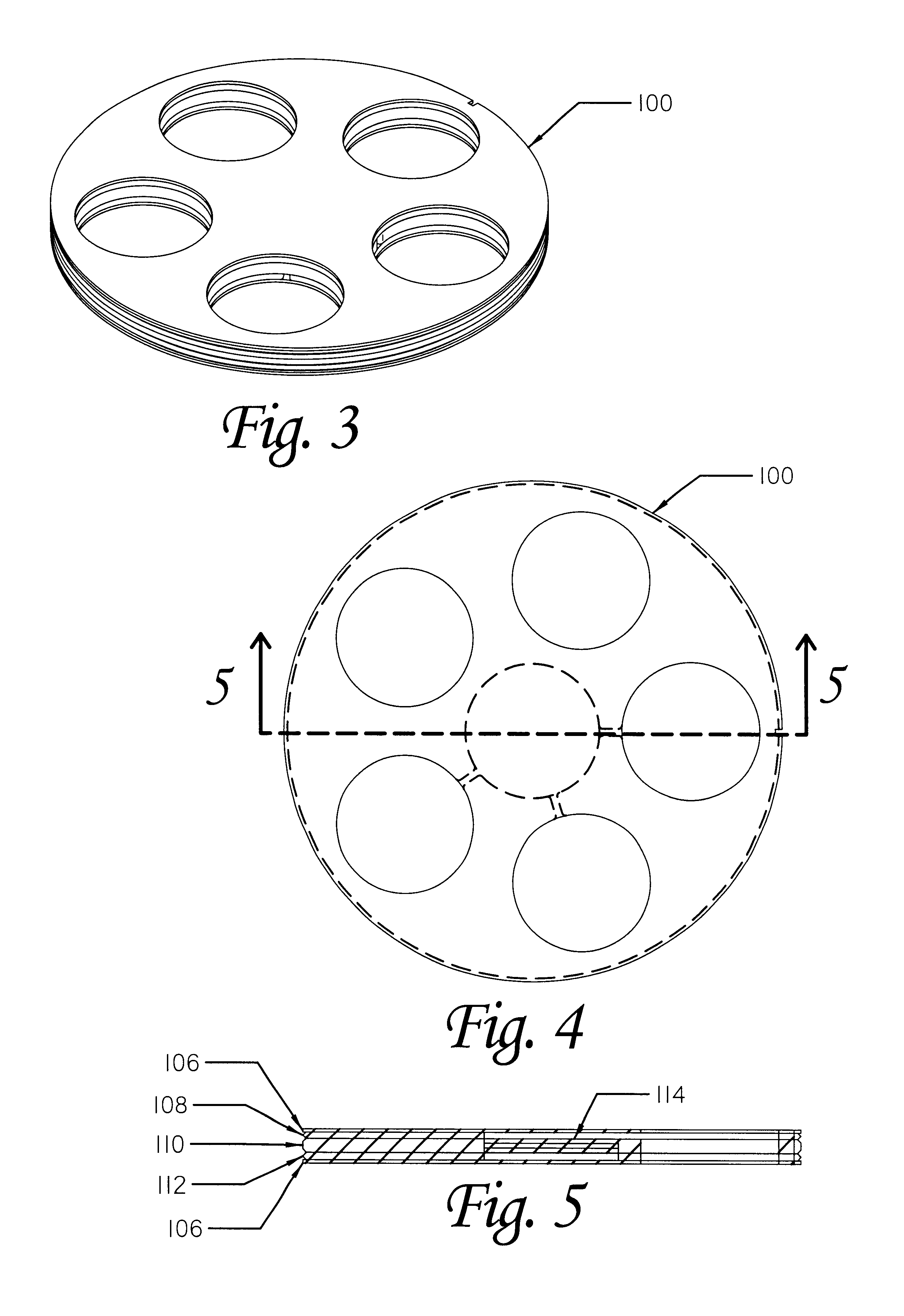
The fuel cells disclosed in the first embodiment above have a wafer diameter of approximately 2 inches and an area of 3.14 square inches. At the assumed power density and size, each fuel cell will produce just over 5 watts / hour of electricity and 26 BTU / hour of thermal energy. The target output of 700 BTU / hr / ft will require approximately 27 fuel cells per linear foot. (Assuming 100% transfer to the deposit.) This implies a thickness of approximately 0.44 in. per cell which is readily achievable.

Of course, different values for thermal output desired, power density and efficiency of the fuel cells, etc. will result in different desired fuel cell size and / or spacing.

The relative thermodynamic and economic advantages of the present invention can be clearly illustrated by contrasting the results of an example application using electrical resistance heaters.

In the example application, the target formation to be heated is an oil shale formation 500 feet thick, averaging 25 gallons of oil p...


PUM

PropertyMeasurementUnit
depthsaaaaaaaaaa
heightaaaaaaaaaa
diameteraaaaaaaaaa

Abstract

A fuel cell based subterranean heater for mineral extraction, in situ decontamination, or other applications. The fuel cells are preferably stacked within a casing which is then inserted into a hole bored, or otherwise formed, into the formation to be heated. Conduits within the casing, and preferably formed by adjacent, aligned holes formed through the plates of the individual fuel cells supply fuel and air and extract exhaust gases. An optional manifold is used to span the overburden without applying heat to it directly. The manifold may also function as a heat exchanger between incoming and exhaust gases. Preferably the fuel cell is fueled by gases produced by the formation and also generates electricity which is available for use or export.

Description

1. Field of the inventionThe present invention relates to the field of devices for heating a subterranean formation.2. Background InformationThe utility and desirability of applying heat to subterranean formations are well known. There are numerous applications, including oil production and remediation of contaminated soils. In many instances it is desirable to heat thick underground sections as uniformly, efficiently, and economically as possible. There are vast deposits of hydrocarbons all over the world, including oil shales, tar sands, and oil-bearing diatomites that will yield combustible gases and oil when heated. There are thousands of sites that have been contaminated by pollutants that can be driven out of the soil or decomposed in place by the application of heat. There may be numerous other uses for the application of subterranean heat as well, including, but not limited to: the accelerated digestion of landfills, thawing of permafrost, gasification of coal, production of...

Claims


Application Information

Patent Timeline
Patent Type & Authority Patents(United States)
IPC IPC(8): E21B43/24E21B43/16E21B41/00H01M8/24H01M8/04H01M8/00
CPCE21B41/0085H01M8/04014H01M8/2425H01M8/247E21B43/24H01M2250/405Y02E60/50Y02B90/16H01M8/2475Y02P90/40Y02B90/10H01M8/2432H01M8/243
Inventor SAVAGE, MARSHALL T.
Owner IEP TECH INC
Why Eureka
Try Eureka