Method for creating correction parameter for posture detecting device, device for creating correction parameter for posture detecting device, and posture detecting device

a technology of posture detection and correction parameter, which is applied in the direction of turn-sensitive devices, instruments, surveying instruments, etc., can solve the problems of detection value errors of posture detection devices, and achieve the effect of easy parallelization, detection value, and convenient security

Inactive Publication Date: 2011-08-18
SEIKO EPSON CORP
View PDF5 Cites 12 Cited by
  • Summary
  • Abstract
  • Description
  • Claims
  • Application Information

AI Technical Summary

Benefits of technology

[0016]Since the above correction parameter creation method uses the jig that is formed in the shape of a rectangular parallelepiped, the posture detection device can be easily secured on the first side so that the first axis, the second axis, and the third axis perpendicularly intersect the first side, the second side, and the third side of the jig, respectively. Since the turntable is installed so that the upper side of the turntable is horizontal, the first axis, the second axis, or the third axis can be easily made parallel to the vertical direction by merely securing the side of the jig opposite to the second side, the third side, or the first side on the upper side of the turntable. The detection values of the acceleration sensors or the angular velocity sensors can be easily and quickly acquired by stopping or rotating the turntable in a state in which the first axis, the second axis, or the third axis is parallel to the vertical direction.
[0017]Specifically, since the rotation direction of the turntable is fixed by initially installing the turntable so that the upper side is horizontal, the setting time for acquiring the detection values about the X-axis, the Y-axis, and the Z-axis can be significantly reduced. Therefore, the correction parameters for correcting errors in the detection values due to the installation angle errors of the sensors can be inexpensively created.

Problems solved by technology

If the posture detection device is not mounted so that the detection axes of the sensors are parallel to three axes of an orthogonal coordinate system that indicates the posture angle of the head, the detection values of the posture detection device include an error due to the installation angle errors.

Method used


Image

  • Method for creating correction parameter for posture detecting device, device for creating correction parameter for posture detecting device, and posture detecting device
  • Method for creating correction parameter for posture detecting device, device for creating correction parameter for posture detecting device, and posture detecting device
  • Method for creating correction parameter for posture detecting device, device for creating correction parameter for posture detecting device, and posture detecting device

Examples


Embodiment Construction

[0068]Exemplary embodiments of the invention are described in detail below with reference to the drawings. Note that the following embodiments do not unduly limit the scope of the invention as stated in the claims. Note that all of the elements described below should not necessarily be taken as essential elements of the invention.

[0069]In the following embodiments, the first axis, the second axis, and the third axis respectively correspond to an X-axis, a Y-axis, and a Z-axis. Note that the first axis, the second axis, and the third axis may have an arbitrary relationship with the X-axis, the Y-axis, and the Z-axis.

1. Posture Detection Device

1-1. Configuration of Posture Detection Device

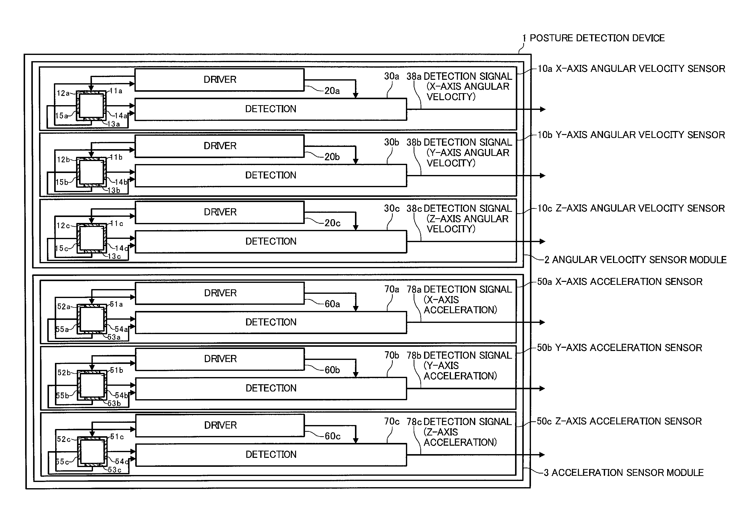
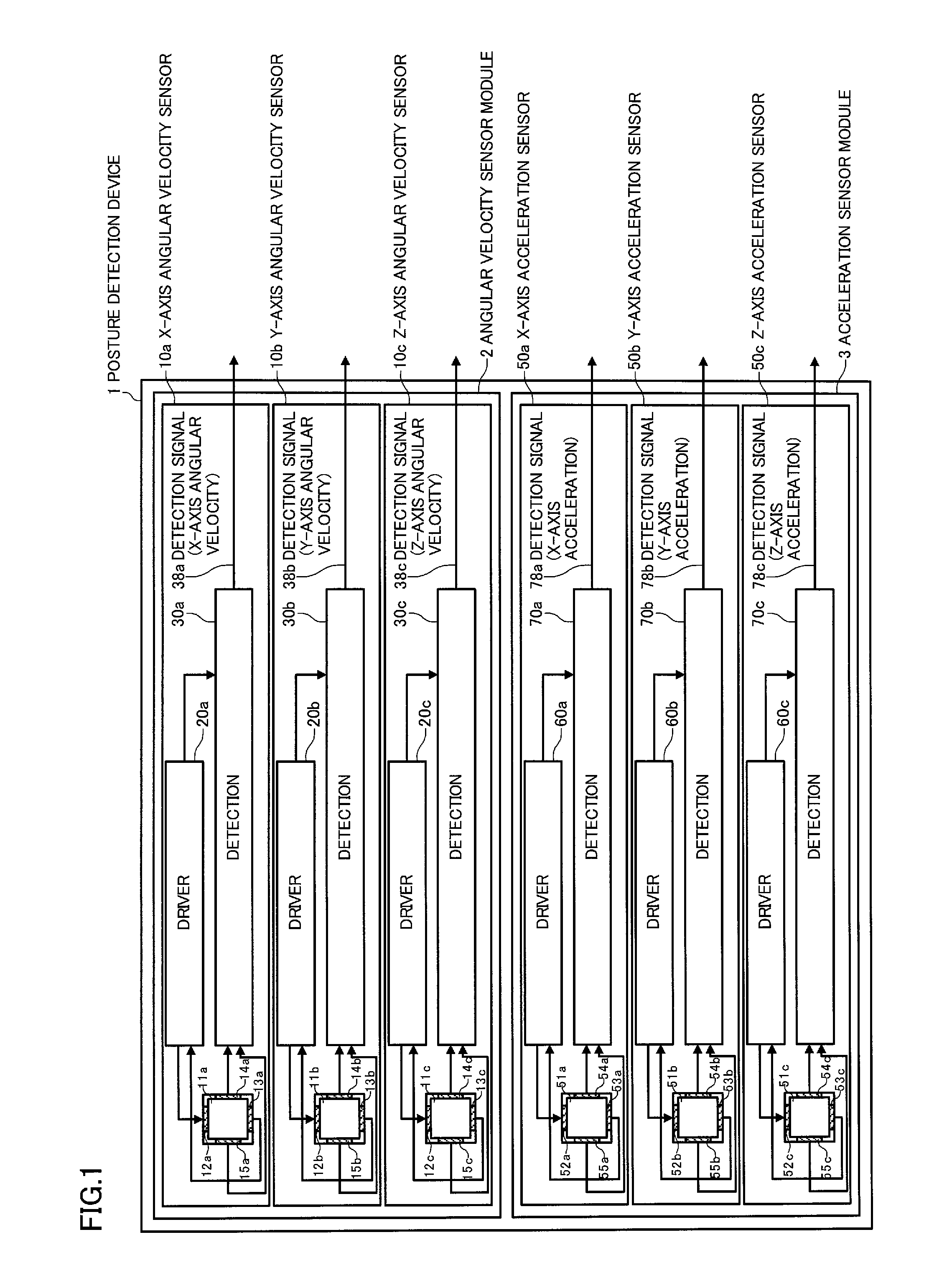
[0070]FIG. 1 is a diagram illustrating an example of the configuration of a posture detection device to which a correction parameter creation method according to one embodiment of the invention is applied.

[0071]As illustrated in FIG. 1, a posture detection device 1 according to one embodiment of the ...


PUM


Abstract

A turntable (230) is installed so that an upper side (231) of the turntable is horizontal (S10). A posture detection device (1) is secured on a side (211) of a cubic jig (210) so that an X-axis (first axis) perpendicularly intersects a side (212) (second side), a Y-axis (second axis) perpendicularly intersects a side (213) (third side), and a Z-axis (third axis) perpendicularly intersects the side (211) (first side) (S12). The side of the cubic jig opposite to the side (212), (213), or (211) is sequentially secured on the upper side of the turntable (S14, S20, and S26). Detection values of the posture detection device are acquired in a state in which the turntable is stationary or rotated at a predetermined angular velocity (S16, S18, S22, S24, S28, and S30), and correction parameters are created (S32).

Description

TECHNICAL FIELD[0001]The present invention relates to a correction parameter creation method that generates correction parameters for correcting detection values of a posture detection device including sensors that detect three-axis angular velocities or three-axis accelerations to detection values in a predetermined orthogonal coordinate system, a correction parameter creation device, and a posture detection device having a correction function.BACKGROUND ART[0002]A posture detection device that detects the posture of an object using angular velocity sensors or acceleration sensors has been used for various applications. For example, JP-A-9-106322 discloses a head mount display that detects the posture of the head of the user, and changes an image displayed on the display in synchronization with the movement of the head of the user so that the user can experience a virtual space. The head mount display disclosed in JP-A-9-106322 displays an image based on the posture angle of the he...

Claims


Application Information

Patent Timeline
Patent Type & Authority Applications(United States)
IPC IPC(8): G06F19/00G01B21/22G01C15/00G01C19/00G01C19/56G01C19/5614G06F3/0346
CPCG01B21/045G01C19/56G06F3/012G01P21/00G01C25/005
Inventor UDAGAWA, HIROFUMIKOBAYASHI, YOSHIHIRO
Owner SEIKO EPSON CORP
Why Eureka
Try Eureka