Low cost and flexible energy management system

a technology of energy management system and low cost, applied in the field of energy management, can solve the problems of low flexibility, no active control, high consumer cost,

Active Publication Date: 2011-08-18
HAIER US APPLIANCE SOLUTIONS INC
View PDF87 Cites 146 Cited by
  • Summary
  • Abstract
  • Description
  • Claims
  • Application Information

AI Technical Summary

Problems solved by technology

Currently Utility companies commonly charge a flat rate for energy, but with the increasing cost of fuel prices and high energy usage during certain parts of the day, Utility companies have to buy more energy to supply consumers during peak demand.
However, there is no active control beyond the mere on / off switching.
Similarly, known systems do not communicate directly with the appliance using a variety of communication methods and protocols, nor is a modular and standard method created for communication devices to interface and to communicate selectable operational modes to the main controller of the appliance.
Both of the current existing types have significant disadvantages due to high consumer cost, low flexibility and increased system complexity.
The first category requires a large upfront cost to the consumer, because the cost of providing an integrated display on the HEM very expensive.
In addition, the electronics required to drive the display is complex and expensive.
The second category of HEM involves a substantial cost to provide the server infrastructure and data transfer.
In addition, this type of HEM must be connected continuously with a remote server otherwise energy data logging and energy saving commands for the devices in the home will be lost during service disruptions.
Therefore this second configuration is very limiting in areas where Internet penetration is very low
These HEMs do not take into consideration that data bandwidth required to support a network of energy consuming devices is much smaller than the data bandwidth required for the networking of consumer electronics products, which is usually high bandwidth and high speed.
The networking standards, including the physical layer, networking layer and application layers are therefore not optimized for the end use.

Method used


Image

  • Low cost and flexible energy management system
  • Low cost and flexible energy management system
  • Low cost and flexible energy management system

Examples


Embodiment Construction

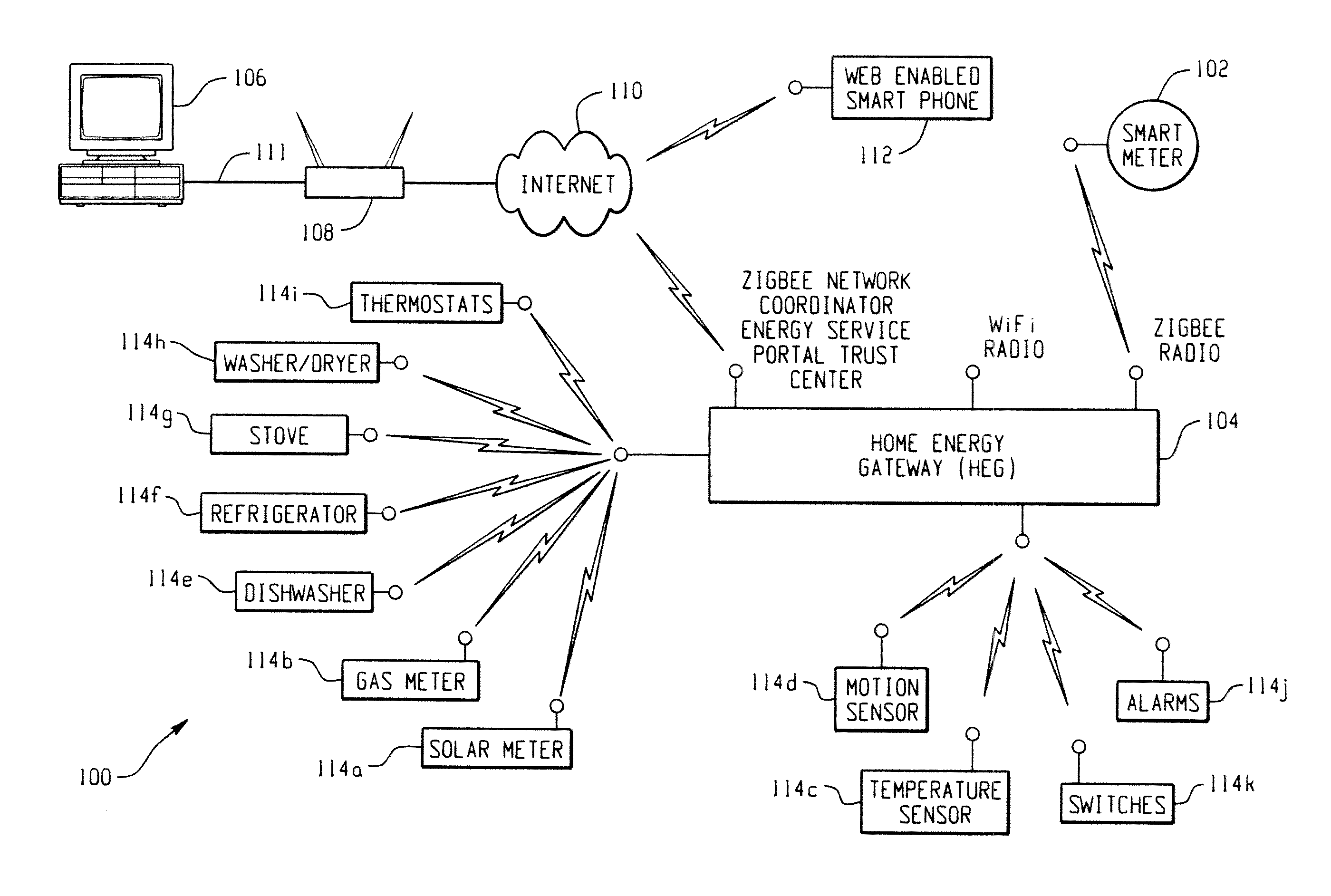
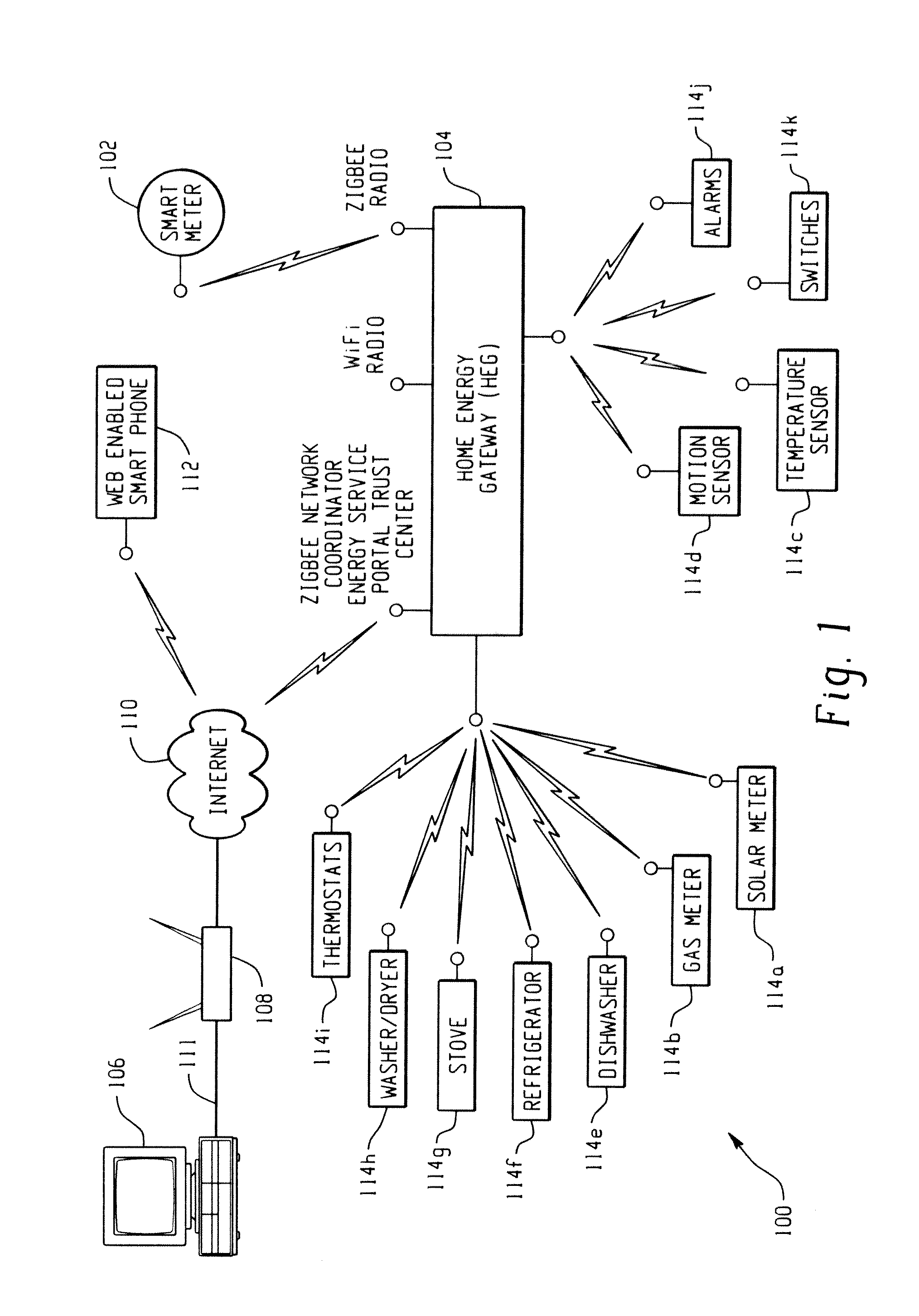
[0028]FIG. 1 is an exemplary implementation of a home / premises energy management system 100 according to the present application.

[0029]The main source of information flow for the home is shown as smart electric meter 102 acting as trust center, coordinator, and / or and energy service portal (ESP), and which is configured in operative connection / communication with a home energy gateway (HEG) 104 of the present application.

[0030]It is well known that the functions of smart meter 102 may be separated into different devices. For example, if the home does not have a smart meter 102—so the electric meter functions only as a meter to provide consumption information—other components can be used to provide the additional capabilities. For example, homes without smart meter 102, can have the metering functionality of smart meter 102 replaced with a simple radio and current transformer (CT) configuration. Also, there are devices that can be placed on the outside of the meter to communicate cons...


PUM


Abstract

A premises data management system includes a first communication network configured to transmit and receive data to and from a user interface. Another communication network is configured to access data from and provides data to accessories within the premises management system. A gateway of the system includes a first interface channel and another interface channel. The gateway receives the data from the first communication network, via the first interface channel. The gateway reformats the data from the first communication network for communication to the other communication network via the other interface channel. The gateway also requests data from the accessories via the other interface channel and replies to the user interface via the first interface channel.

Description

INCORPORATION BY REFERENCE[0001]This application claims the benefit of priority to U.S. Provisional Patent Application No. 61 / 304,712, filed Feb. 15, 2010, entitled “Low Cost And Flexible Energy Management System”, by Venkatakrishnan et al.; U.S. patent application Ser. No. 12 / 853,342, filed Aug. 10, 2010, entitled “Sub-Metering Hardware For Measuring Energy Data Of Energy Consuming Device”, by Kobraei et al.; and U.S. patent application Ser. No. 12 / 853,334, filed Aug. 10, 2010, entitled “Diagnostics Using Sub-Metering Device” by Kobraei et al., the disclosures of each of which are incorporated herein by reference in their entireties.BACKGROUND OF THE DISCLOSURE[0002]The following disclosure relates to energy management, and more particularly to a premises energy management system for management of household consumer appliances, as well as other energy consuming devices and / or systems found in the home, at times called herein as accessories or network accessories. The present disclo...

Claims


Application Information

Patent Timeline
Patent Type & Authority Applications(United States)
IPC IPC(8): G06F15/16G06F9/44
CPCG06Q50/06G06Q10/06H02J2310/12
Inventor VENKATAKRISHNAN, NATARAJANFINCH, MICHAEL FRANCISBULTMAN, ROBERT MARTENWORTHINGTON, TIMOTHY DALEBINGHAM, DAVID C.DRAKE, JEFF DONALDWATTS, WILLIAM ANTHONYNOLAN, KEVIN FARRELLYEMERY, CATHY DIANEKOBRAEI, HENRY
Owner HAIER US APPLIANCE SOLUTIONS INC
Why Eureka
Try Eureka