Drawing device

a drawing device and drawing technology, applied in the field of drawing devices, can solve the problems of limited design freedom of drawing devices, and achieve the effects of small damping force, increased damping durability, and large damping for

Inactive Publication Date: 2011-08-25
SUGATSUNE IND CO LTD
View PDF6 Cites 15 Cited by
  • Summary
  • Abstract
  • Description
  • Claims
  • Application Information

AI Technical Summary

Benefits of technology

[0011]According to the present invention, the linear damper is first operated for generating a relatively large damping force, and then, the damper is switched to the rotary damper, which is operated for generating a relatively small damping force. With this structure, it is possible to generate the damping forces in accordance with the strength of an elastic force of the elastic member. As the two dampers operate one by one from start to finish of the operation of the drawing device, it is not necessary to increase the durability of the dampers. Further, if the rotary damper is used to increase the damping force, the rotary damper needs to have a larger diameter and there arises a problem that the drawing device cannot be accommodated in the narrow guide rail and the design freedom of the drawing device is limited. However, according to the present invention, as the elongating and extendable linear damper is used, the drawing device can be accommodated in the narrow guide rail.

Problems solved by technology

Further, if the rotary damper is used to increase the damping force, the rotary damper needs to have a larger diameter and there arises a problem that the drawing device cannot be accommodated in the narrow guide rail and the design freedom of the drawing device is limited.

Method used


Image

  • Drawing device
  • Drawing device
  • Drawing device

Examples


Embodiment Construction

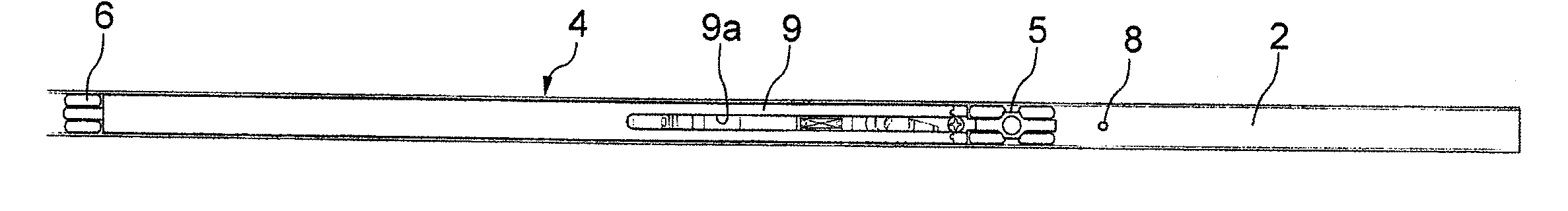
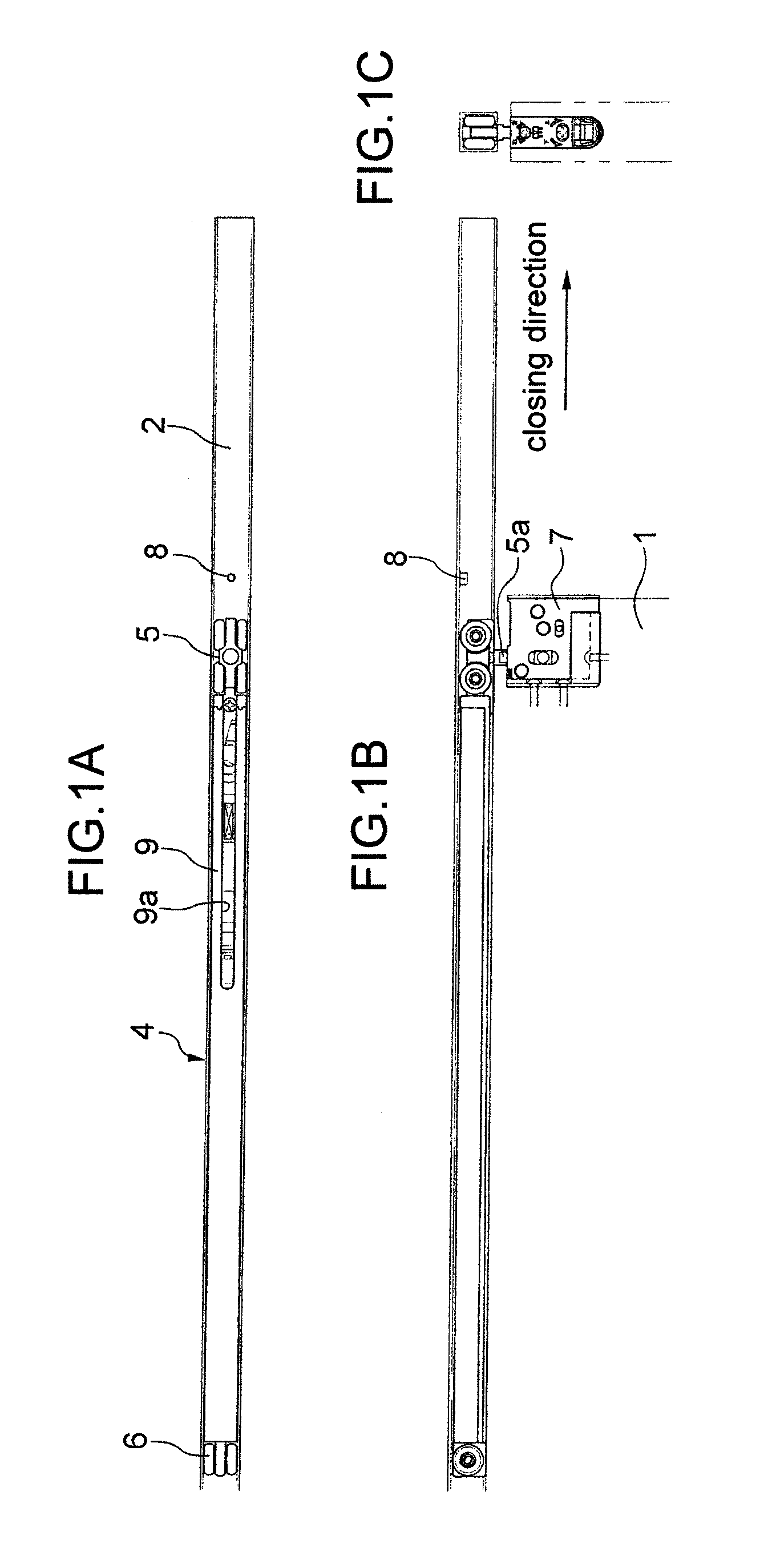
[0032]With reference to the drawings, an exemplary embodiment of the present invention will be described below. FIGS. 1A to 1C are outline views of a drawing device. On the top frame of a sliding door 1, a guide rail 2 is fixed that extends in the moving direction of the sliding door 1. A drawing device main body 4 also elongating is inserted into the guide rail 2 and can move smoothly in the guide rail 2 by door rollers 5 and 6 which are provide at the longitudinal-direction respective ends of the drawing device main body 4. The sliding door 1 suspends from the drawing device main body 4. The drawing device main body 4 moves in the guide rail 2 in conjunction with movement in opening and closing directions of the sliding door 1. The sliding door 1 is connected to the door roller 5 via a position adjusting unit 7. The position in the vertical direction and width direction of the sliding door 1 relative to the drawing device main body 4 can be adjusted by the position adjusting unit ...


PUM


Abstract

Provided is a drawing device that is capable of generating a damping force in accordance with the strength of a biasing force of an elastic member without increasing durability. The drawing device has a linear damper 24 of which a rod is extendable relative to a damper main body and a rotary damper 25 of which a rotation axis is rotatable relative to the damper main body. When a slider 14 of a drawing device main body 4 moves relative to a base 12 of the drawing device main body 4 in the longitudinal direction by the biasing force of the elastic member 15, first, the linear damper 24 starts to operate thereby generating the damping force, then, the linear damper 24 is switched with the rotary damper 25 and the rotary damper 25 starts to operate thereby generating the damping force.

Description

BACKGROUND OF THE INVENTION[0001]1. Field of the Invention[0002]The present invention relates to a drawing device that generates a force for assisting manual one-way movement of an opening / closing body such as a sliding door, a folding door or a drawer.[0003]2. Related Art[0004]A sliding door is sometimes provided with a drawing device that generates an assisting force in a closing direction for the sliding door that moves in the closing direction. A typical drawing device is called a self-closing device, and when the sliding door is moved manually along the guide rail in the closing direction and reaches a certain point, a biasing force in the closing direction by the elastic member is exerted on the sliding door. Then, the sliding door moves automatically in the closing direction and stops at a fully closed position (see, for example, Japanese Patent Application Laid-open No. 2008-285933).[0005]On an upper part of a frame, a guide rail is attached that extends in the moving direct...

Claims


Application Information

Patent Timeline
Patent Type & Authority Applications(United States)
IPC IPC(8): E05F11/02E05F5/04
CPCE05Y2800/24E05Y2800/244E05F5/003E05Y2800/22Y10T16/615E05Y2201/264E05Y2900/132Y10T16/27E05F1/16E05D15/063E05Y2600/456A47B88/40
Inventor IWAKI, JUNPEI
Owner SUGATSUNE IND CO LTD
Why Eureka
Try Eureka