Laser Welding Method, Laser-Welded Joint, Outside Sheathing Panel, and Body Structure for Rolling Stock

a laser welding and body structure technology, applied in welding/soldering/cutting articles, manufacturing tools, transportation and packaging, etc., can solve the problems of reducing the strength against general buckling and local buckling, the inability to obtain theoretical buckling strength, and the inability to achieve buckling strength, etc., to achieve the effect of improving dimensional accuracy, reducing buckling strength, and improving body structure stiffness

Active Publication Date: 2011-08-25
KAWASAKI RAILCAR MFG CO LTD
View PDF15 Cites 17 Cited by
  • Summary
  • Abstract
  • Description
  • Claims
  • Application Information

AI Technical Summary

Problems solved by technology

However, since such angled joining is complicated in the manufacture, the reinforcement members are actually positioned horizontally (in the rail direction) or vertically.
However, such stainless steel body structures as mentioned above have several problems.
(i) A first problem is a lowered strength against general buckling and local buckling.
In this case, it is possible that stress is not decentralized over each reinforcement member as desired and, hence, a theoretical buckling strength cannot be obtained.
Specifically, the stiffener panel may have an antiplane flexural stiffness lower than the theoretical value, which results in the possibility of occurrence of general buckling caused by a load that is lower than estimated.
Further, initial strain occurs on the outside sheathing due to strain about each spot caused by pressure contact.
Such initial strain also causes local buckling strength to lower largely.
(ii) A second problem is permanent deformation in a stress concentrated portion (on the tensioned side) or local buckling (on the compressed side).
A side construction for commuter cars, in particular, has many openings such as windows and doorways, and stress concentration at the corners of such an opening portion is problematic.
Such stress concentrated portions allow permanent deformation and buckling to occur on the tensioned side and the compressed side, respectively, which will finally lead to failure.
However, the conventional stainless steel body structure assembled by resistance spot welding involves some problems.
In this case, it is possible that stress is not decentralized over the reinforcement plate as desired and, hence, a theoretical buckling strength is not obtained.
Further, even though the reinforcement plate is added, the number of welded spots is increased for joining of the reinforcement plate and, as a result, initial strain occurs in the outside sheathing due to strain about each spot caused by pressure contact and heating.
The provision of such a reinforcement plate may cause local buckling strength to lower on the contrary.
(iii) A third problem is associated with watertightness.
However, it is possible that the seal is broken by aged deterioration of the sealant due to weather and washing to allow water to penetrate into the car.
(vi) A fourth problem is associated with the aesthetic value of outside sheathing (side outside sheathing and end outside sheathing).
The outside sheathing is aesthetically impaired by such strain and impressions.
Impairment of the aesthetic value of the side outside sheathing or end outside sheathing, in particular, will lower the product value.
Though “scorch” on the outside sheathing resulting from spot welding can be eliminated by an electrolytic process, impressions are relatively deep and hence cannot be rendered invisible by polishing or a like process following the joining.
(v) A fifth problem is the complexity of the inside framework.
Accordingly, the count of parts including screw seats, inside framework and fixtures increases and, hence, very much man-hour is required for making and welding of such parts.
In addition, dimensional control for mounting of such parts is complicated because mounting places are not standardized.
However, too large a penetration depth sometimes causes discoloration to occur on the reverse side opposite away from the welding side (back scorch) due to high temperature oxidation or allows the weld bead to be exposed.
With such a penetration depth, joining cannot be achieved at all under the influence of some disturbance.
It is therefore difficult to ensure both the joint quality and the aesthetic quality of the outward appearance at a time.
However, an increase in the plate thickness of the lower plate more than necessary results in a considerable increase in the mass of the resulting structure undesirably.

Method used


Image

  • Laser Welding Method, Laser-Welded Joint, Outside Sheathing Panel, and Body Structure for Rolling Stock
  • Laser Welding Method, Laser-Welded Joint, Outside Sheathing Panel, and Body Structure for Rolling Stock
  • Laser Welding Method, Laser-Welded Joint, Outside Sheathing Panel, and Body Structure for Rolling Stock

Examples


first embodiment

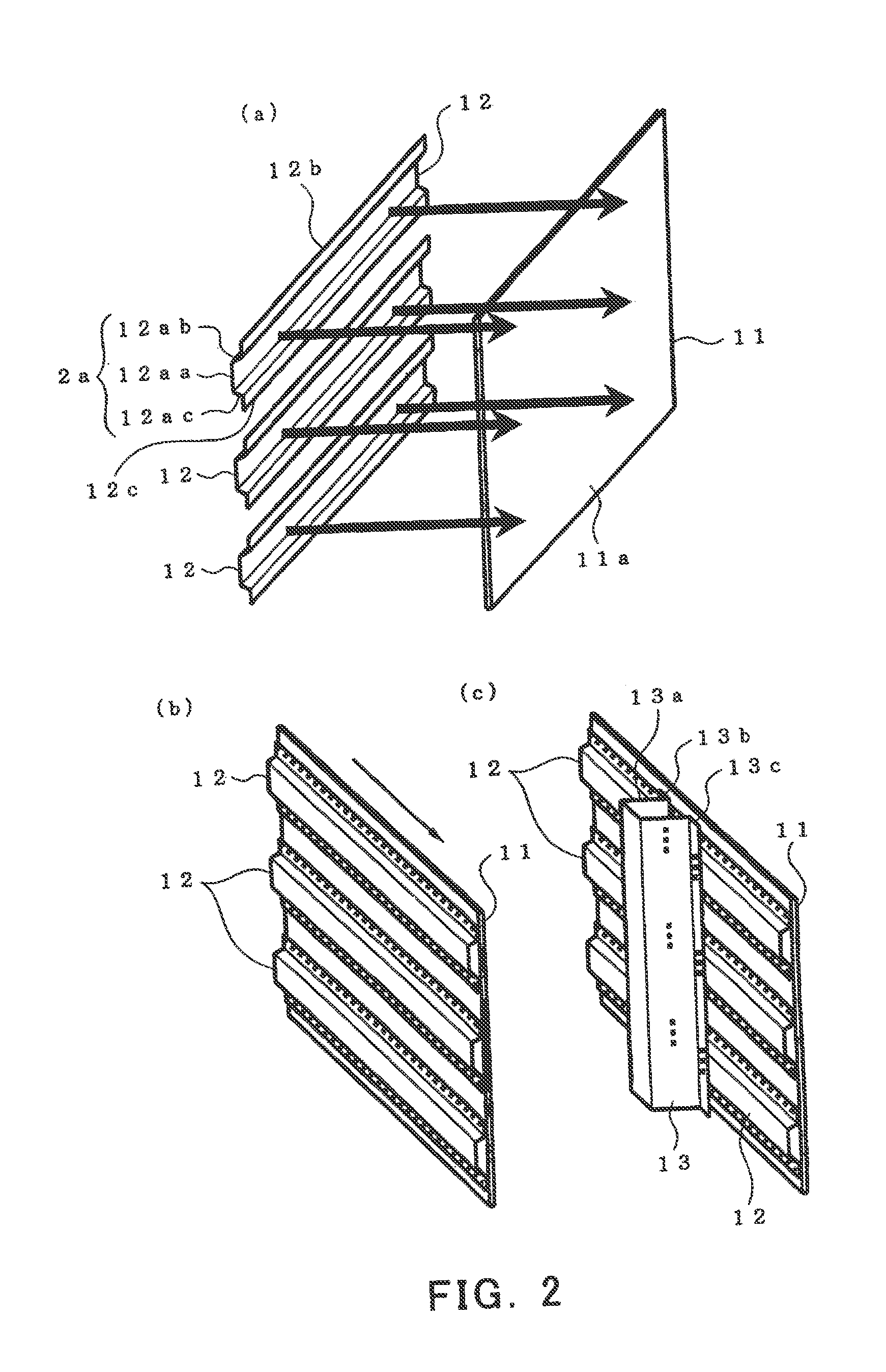
[0152]FIG. 2 illustrates a basic principle based on which a body structure for rolling stock is constructed using a laser-welded joint according to the present invention.

[0153]As shown in FIGS. 2(a) and 2(b), partial penetration laser welding is used to join first reinforcement members 12 each substantially shaped like a hat in section to an inside surface of an outside sheathing 11 (a surface ground material having an outside surface 11a previously polished by a belt grinder substantially in parallel with the direction of a weld line to be formed by laser welding) so that the bottom of a resulting molten pool will not reach the outside surface 11a of the outside sheathing 11. At that time, the outside surface 11a of the outside sheathing 11 has been previously polished substantially in parallel with the direction of a weld line to be formed by laser welding. That is, the direction of the weld line to be formed by laser welding and the direction in which the outside surface 11a has ...

second embodiment

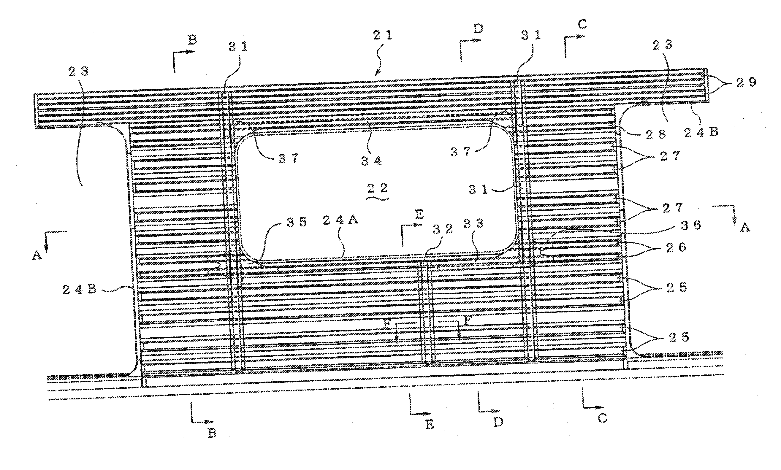
[0174]FIG. 20 is a perspective view showing a body structure for rolling stock according to a second embodiment of the present invention.

[0175]As shown in FIG. 20, the body structure 301 for rolling stock includes right and left side constructions 302, a roof construction 303, front and rear end constructions 304, and an underframe 305. Each of the side constructions 302 has an outside sheathing 306 and outside sheathing reinforcement members 307A and 307B (third reinforcement members) joined to the inside surface of the outside sheathing 306 by laser welding. (The same holds true for the roof construction 303 and the end constructions 304.) The outside sheathing reinforcement member 307A (or 307B) is shaped like a hat in section having a U-shaped part 307Aa having a U-shaped section, and fitting parts 307Ab and 307Ac extending continuously from the opposite end edges of the U-shaped part 307Aa in opposite directions. These fitting parts 307Ab and 307Ac are laser-welded to the outsi...


PUM

PropertyMeasurementUnit
thicknessaaaaaaaaaa
angleaaaaaaaaaa
thickaaaaaaaaaa

Abstract

A body structure for rolling stock is disclosed. The body structure may include an outside sheathing of a side construction, and a plurality of reinforcement members joined to said outside sheathing interiorly of said outside sheathing. Each of said plurality of reinforcement members may include a U-shaped part which is substantially U-shaped in cross-section and two fitting flange parts extending continuously from end edges of the U-shaped part in opposite directions. The fitting flange parts may be joined to said outside sheathing by laser welding, and the U-shaped part of at least one of said plurality of reinforcement members may be smaller in width than the U-shaped part of another of said plurality of reinforcement members provided on another part of said outside sheathing.

Description

CROSS REFERENCE TO RELATED APPLICATIONS[0001]The present application is a divisional of U.S. patent application Ser. No. 11 / 596,834 filed Jan. 30, 2007, entitled “Laser Welding Method, Laser-Welded Joint, Outside Sheathing Panel, and Body Structure for Rolling Stock,” which is the national phase of PCT / JP2005 / 007076 filed Apr. 12, 2005, entitled “Laser Welding Method, Laser Welded Joint, Outer Panel, and Structure for Rolling Stock,” which in turn claims priority to JP2004-147598 filed May 18, 2004 and JP2004-206390 filed Jul. 13, 2004, the entire contents of which are incorporated herein by reference.TECHNICAL HELD[0002]The present invention relates to a laser welding method and a laser-welded joint, as well as an outside sheathing panel and a body structure for rolling stock which are formed by using the method and the joint. The invention is particularly suitable for uncoated body structures for rolling stock or car bodies of buses, trucks and like cars.BACKGROUND ART[0003]Conven...

Claims


Application Information

Patent Timeline
Patent Type & Authority Applications(United States)
IPC IPC(8): B61D17/00B61D17/04B61D17/08B61D17/06B61D17/12B23K26/02B23K26/22B23K26/24B23K26/28
CPCB23K26/023B23K26/22B23K26/246B23K26/28Y02T30/34B23K2201/185B23K2201/24B23K2203/02B61D17/04B23K2201/006B23K26/037B23K26/244B23K2101/006B23K2101/185B23K2101/24B23K2103/02Y02T30/00
Inventor KOMAKI, OSAMUHIRASHIMA, TOSHIYUKIMURATA, TAKAYUKIMARUTANI, TAKEO
Owner KAWASAKI RAILCAR MFG CO LTD
Why Eureka
Try Eureka