Fluid connector latches with profile lead-ins

a technology of lead-ins and connector latches, which is applied in the direction of couplings, other medical devices, pipe elements, etc., can solve the problems of prone to leakage and unwanted disconnection of existing tubing connectors, and achieve the effect of reducing the insertion force requirements of couplings and increasing the amount of for

Active Publication Date: 2011-08-25
NORDSON CORP
View PDF101 Cites 59 Cited by
  • Summary
  • Abstract
  • Description
  • Claims
  • Application Information

AI Technical Summary

Benefits of technology

[0011]Improved female tube connectors are disclosed herein that reduce insertion force requirements for coupling with male connectors. Additionally, the female tube connectors increase the

Problems solved by technology

Existing tubing connectors are prone to leakage and unwanted disconnection when the patient is still receiving treatment via the connected tubes due to

Method used


Image

  • Fluid connector latches with profile lead-ins
  • Fluid connector latches with profile lead-ins
  • Fluid connector latches with profile lead-ins

Examples


Embodiment Construction

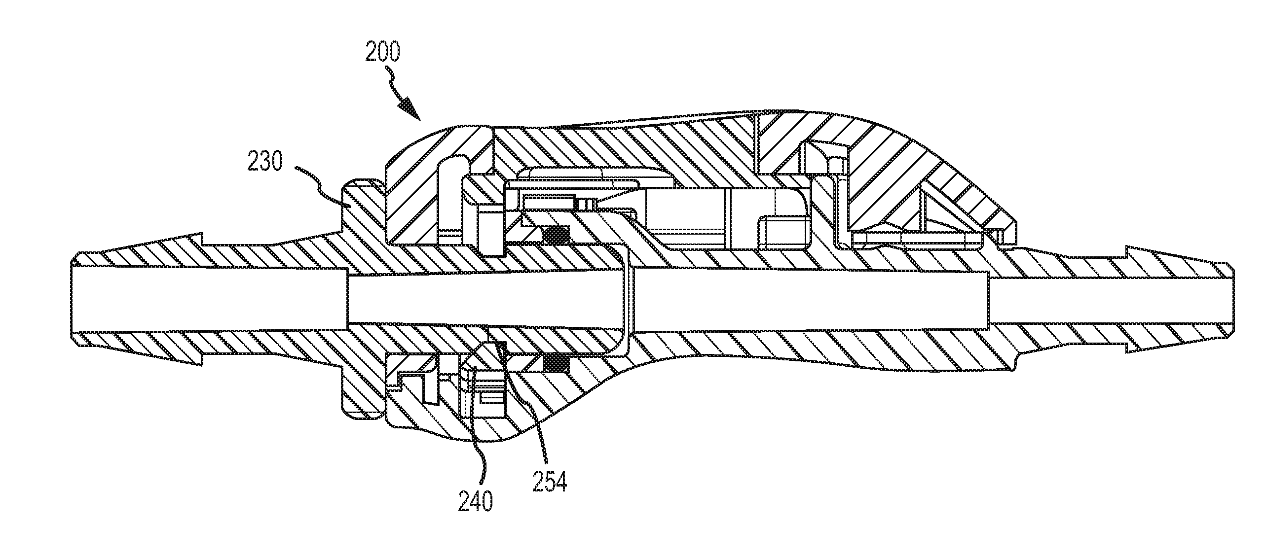
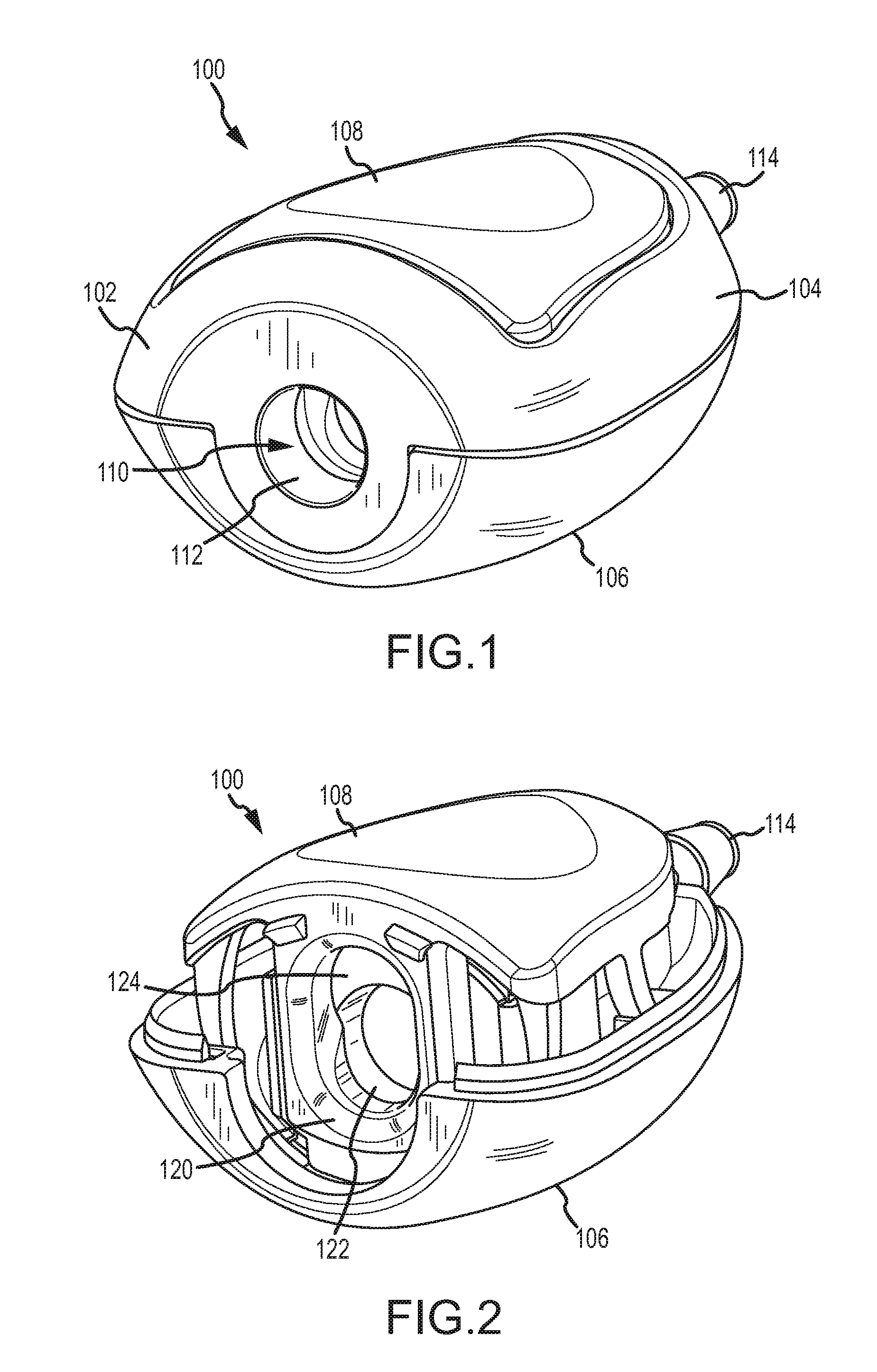
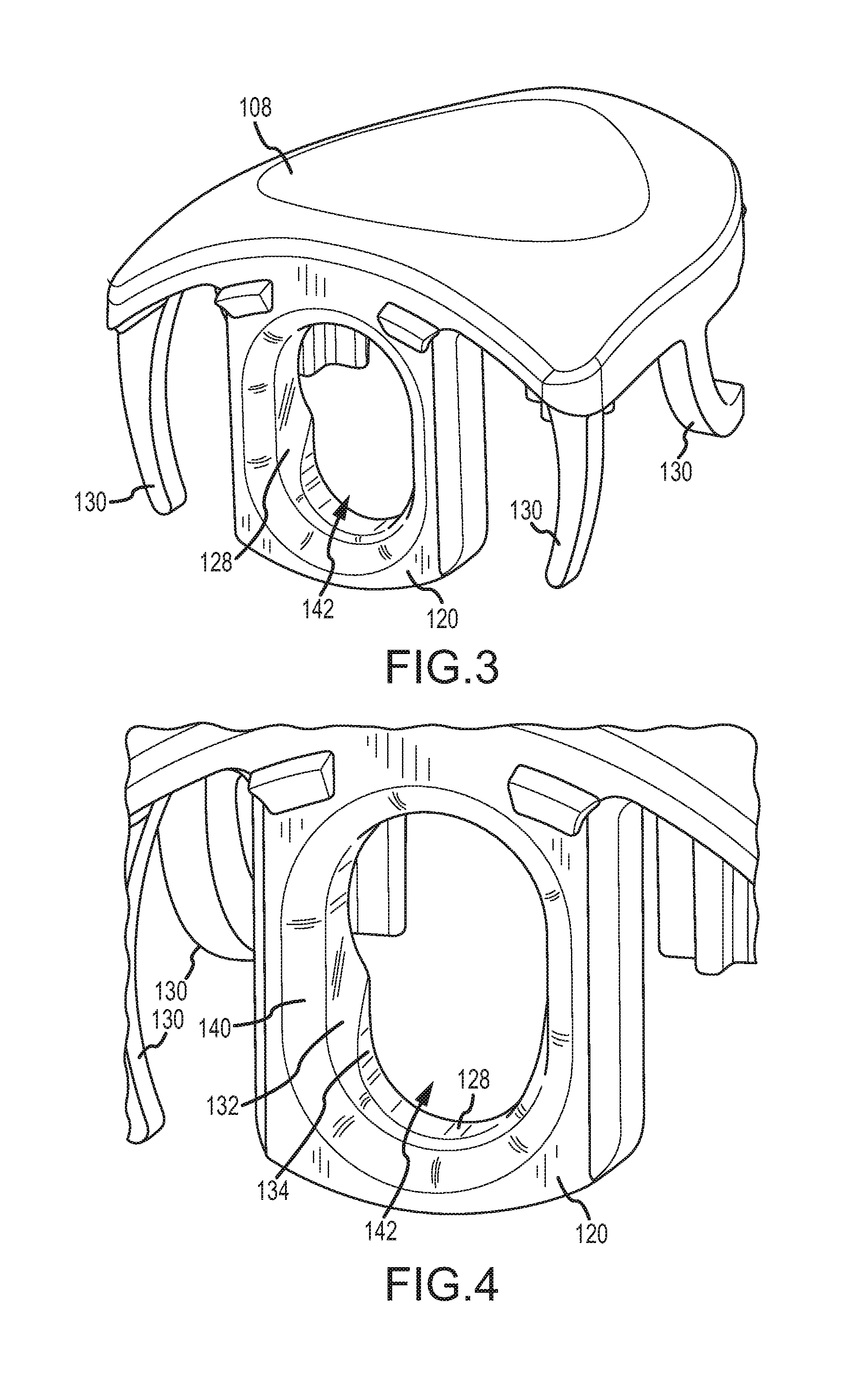
[0034]Embodiments of female receiving connectors in conjunction with male bayonet connectors, may be used to releasably connect sections of tubing. In one embodiment, the female receiving connector includes a latch plate with a profile lead-in that extends upward along the lateral sides of the aperture in the latch plate. The profile lead-in provides extended latching surfaces for the latch plate to secure a male bayonet connector. When the male bayonet connector is inserted into the female receiving connector, a distal end of the male bayonet connector interfaces the profile lead-in, biases the latch plate downward, and lowers a receiving aperture through which the male bayonet connector may pass. The male bayonet connector includes an annular channel that is engaged by the profile lead-in upon sufficient insertion of the male bayonet connector into the female receiving connector.

[0035]The orientations “proximal” and “distal” as used herein have been arbitrarily chosen, and are not...


PUM


Abstract

A female receiving connector for connecting sections of tubing is provided. The female receiving connector includes a housing having a top housing portion and a bottom housing portion coupled to the top housing portion. The female receiving connector also includes a button moveably coupled within the housing. A locking plate is coupled to the button and configured to move with the button. The locking plate has a profile lead-in having an interfacing surface located at a proximal side of the profile lead-in for interfacing a male connector. The interfacing surface extends along at least a portion of at least three sides of an aperture of the locking plate and is tapered along one or more of the at least three sides. Additionally, the profile lead-in includes a locking surface located at a distal side of the profile lead-in for securing the male connector within the housing of the female receiving connector. A substantially flat surface is located between the interfacing surface and the locking surface.

Description

CROSS REFERENCE TO RELATED APPLICATIONS[0001]This application claims the benefit of priority pursuant to 35 U.S.C. §119(e) of U.S. provisional application No. 61 / 361,306 filed 2 Jul. 2010 entitled “Fluid connector latches with profile lead-ins” and U.S. provisional application No. 61 / 289,990 filed 23 Dec. 2009 entitled “Fluid connector latches with profile lead-ins” each of which is hereby incorporated herein by reference in its entirety.[0002]The present application is related to U.S. patent application Ser. No. ______ [Attorney Docket No. P191627.US.03] filed contemporaneously herewith entitled “Button latch with integrally molded cantilever springs”; U.S. patent application Ser. No. ______ [Attorney Docket No. P191625.US.02] filed contemporaneously herewith entitled “Male bayonet connector”; U.S. design patent application Ser. No. 29 / 352,637 filed 23 Dec. 2009 entitled “Female dual lumen connector”; and U.S. design patent application Ser. No. 29 / 351,665 filed 9 Dec. 2009 entitled...

Claims


Application Information

Patent Timeline
IPC IPC(8): F16L37/00
CPCA61M39/10A61M39/1011F16L37/56A61M2039/1088F16L37/0841A61M39/105F16L37/084F16L37/086F16L55/00
Inventor WHITAKER, CARL T.LEWIS, PETER D.
Owner NORDSON CORP
Why Eureka
Try Eureka