Over-voltage suppression apparatus

a technology of over-voltage and apparatus, which is applied in the direction of switch power arrangements, contact mechanisms, relays, etc., can solve the problems of affecting the insulation of equipment installed in the system, being difficult in practice to find the voltage between contacts from a function approximation, and being difficult in itself to approximate the voltage oscillation of the line by a function. , to achieve the effect of suppressing over-voltag

Active Publication Date: 2011-08-25
KK TOSHIBA
View PDF3 Cites 5 Cited by
  • Summary
  • Abstract
  • Description
  • Claims
  • Application Information

AI Technical Summary

Benefits of technology

[0027]With the present invention, an over-voltage suppression apparatus can be provided that makes it possible to suppress over-voltage generated when a circuit breaker is closed, even when the voltage between contacts of the circuit breaker is of multifrequency waveform.

Problems solved by technology

There is a risk that generation of such a large over-voltage may affect the insulation of equipment installed in the system.
However, there are the following respective problems with the methods of over-voltage suppression described above.
In this case, it is in itself difficult to approximate the voltage oscillations of the line by a function.
Accordingly, it is extremely difficult in practice to find the voltage between contacts from a function approximation.
Furthermore, the following problems are experienced if the timing for circuit breaker closure is obtained by measuring the time between the voltage between contacts between zero points of the circuit breaker.

Method used


Image

  • Over-voltage suppression apparatus
  • Over-voltage suppression apparatus
  • Over-voltage suppression apparatus

Examples


first embodiment

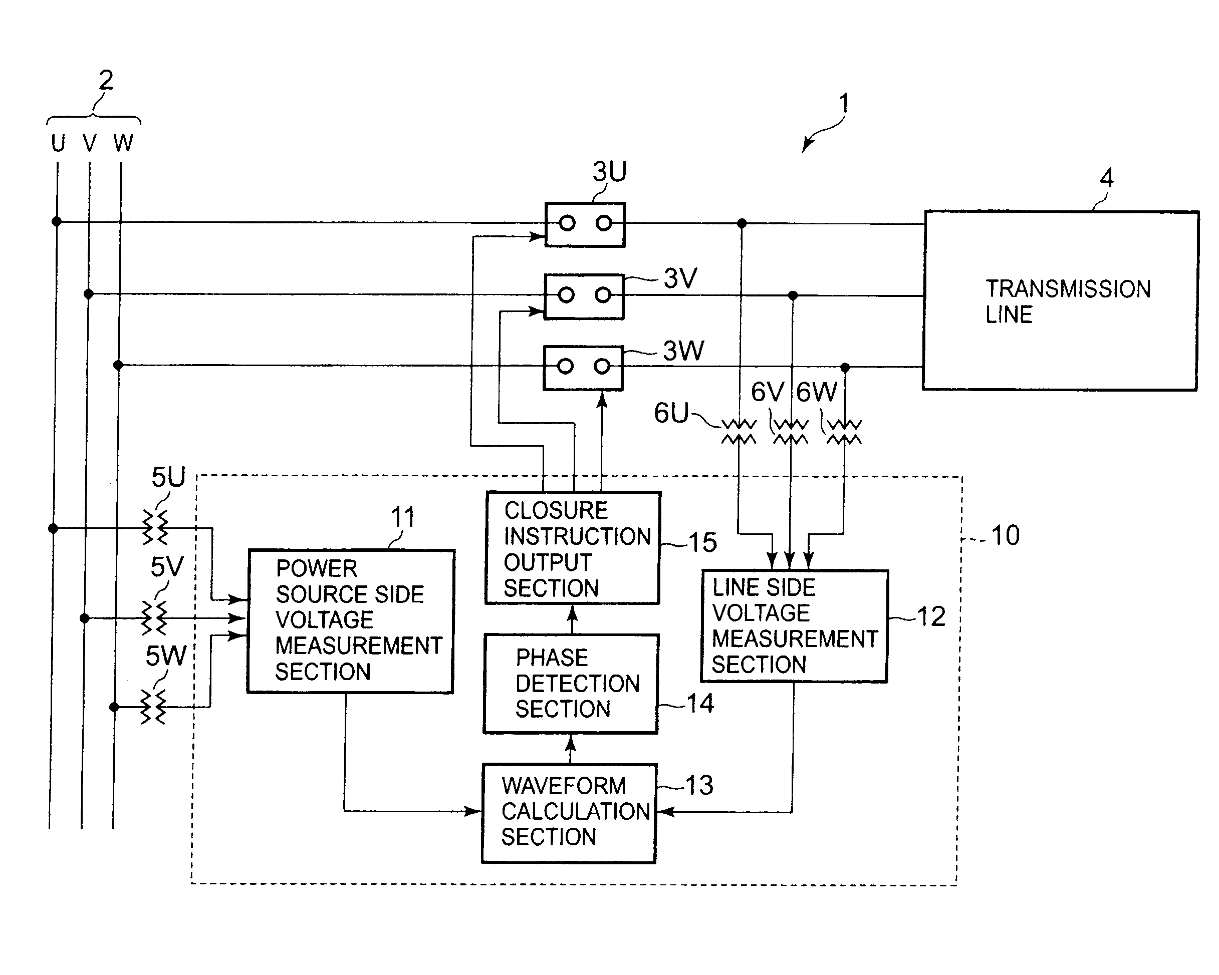
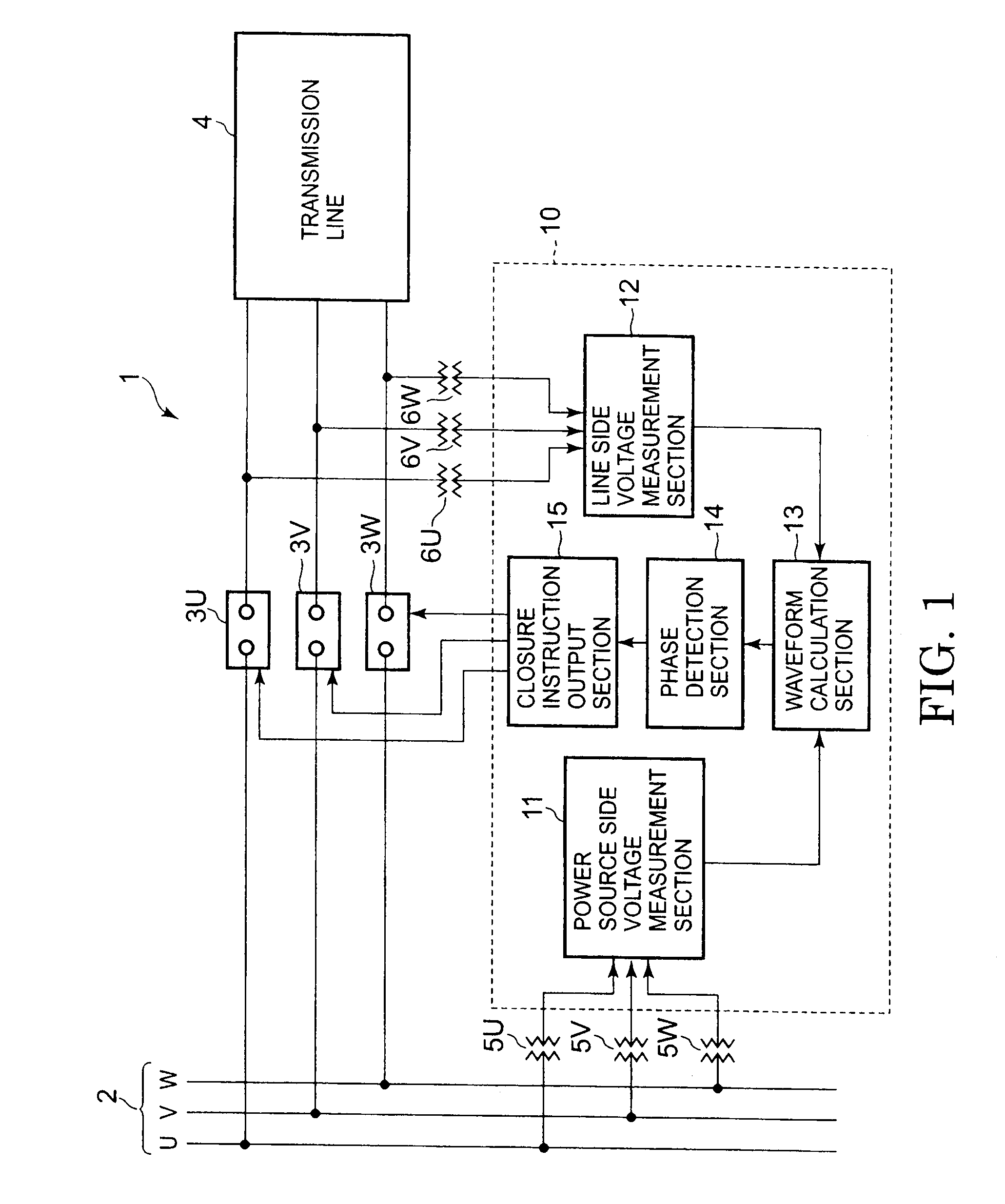
[0054]FIG. 1 is a layout diagram showing the layout of a power system 1 to which an over-voltage suppression apparatus 10 according to a first embodiment of the present invention has been applied. It should be noted that corresponding portions in the following Figures are given the same reference numerals and further detailed description is dispensed with i.e. the description will focus on the differences between such portions. Repeated description will be avoided in the same way in the following embodiments.

[0055]A power system 1 comprises: a power source bus 2, three-phase circuit breakers 3U, 3V and 3W; a transmission line 4; three-phase power source side voltage detectors 5U, 5V and 5W, three-phase line side voltage detectors 6U, 6V and 6W, and an over-voltage suppression apparatus 10.

[0056]The power source bus 2 is a bus of the power source system comprising a three-phase AC power source comprising a U phase, V phase and W phase.

[0057]The transmission line 4 is electrically con...

second embodiment

[0093]FIG. 9 is a layout diagram showing the construction of a power system 1A to which an over-voltage suppression apparatus 10A according to a second embodiment of the present invention has been applied.

[0094]The power system 1A has a construction wherein, in the power system 1 according to the first embodiment shown in FIG. 1, the over-voltage suppression apparatus 10 is replaced by an over-voltage suppression apparatus 10A. In other respects, the power system 1A is the same as the power system 1 according to the first embodiment.

[0095]FIG. 10 is a layout diagram showing the construction of an over-voltage suppression apparatus 10A according to this embodiment.

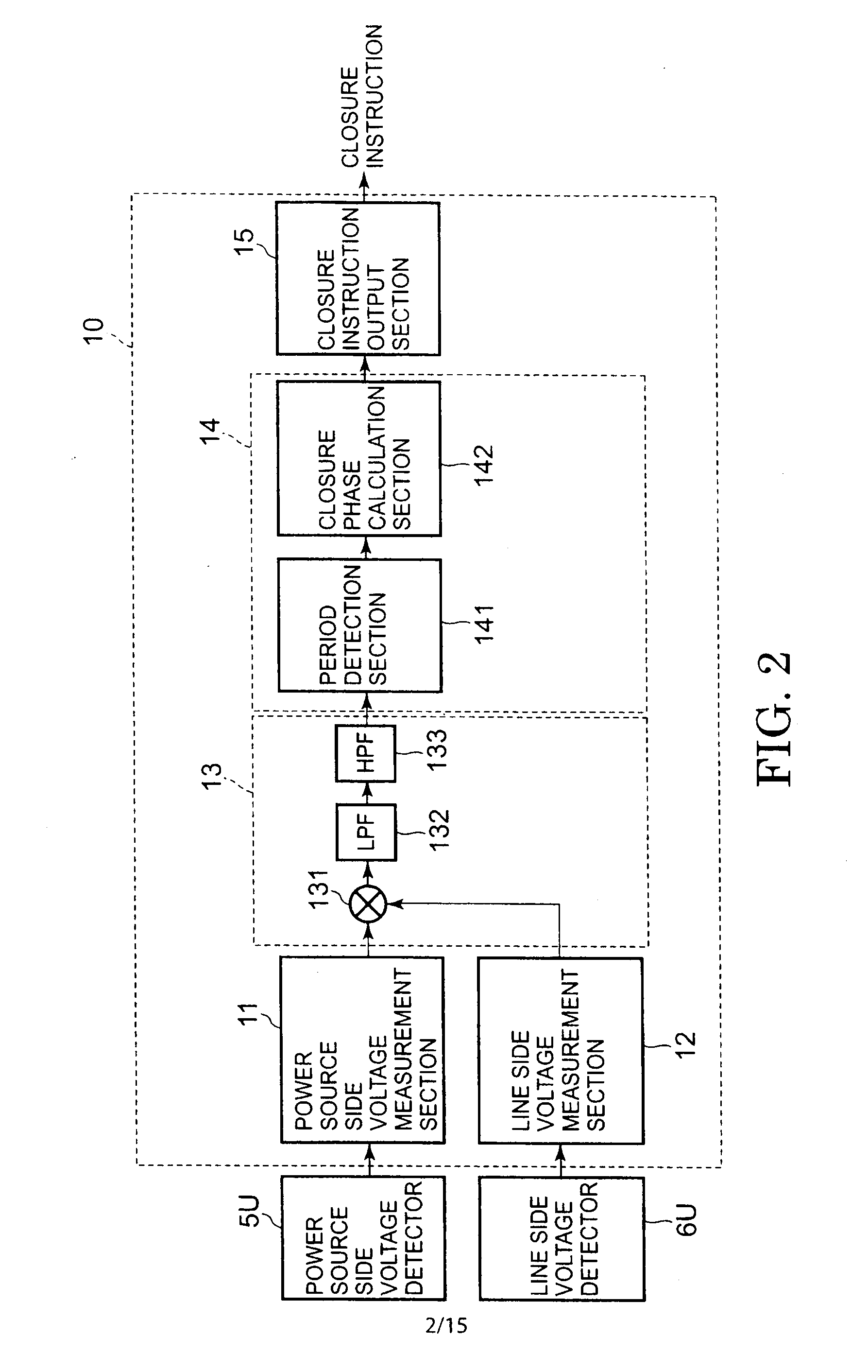
[0096]The over-voltage suppression apparatus 10A has a construction wherein, in the over-voltage suppression apparatus 10 according to the first embodiment shown in FIG. 2, a waveform calculation section 13A is provided instead of the waveform calculation section 13. In other respects, the over-voltage suppression apparatus...

third embodiment

[0117]FIG. 17 is a layout diagram showing the layout of a power system 1B to which the over-voltage suppression apparatus 10B according to a third embodiment of the present invention has been applied.

[0118]The power system 1B has a construction wherein, in the power system 1 according to the first embodiment shown in FIG. 1, an over-voltage suppression apparatus 10B is provided instead of the over-voltage suppression apparatus 10. In other respects, the power system 1B is the same as the power system 1 according to the first embodiment.

[0119]FIG. 18 is a layout diagram showing the construction of an over-voltage suppression apparatus 10B according to this embodiment.

[0120]The over-voltage suppression apparatus 10B has a construction wherein, in the over-voltage suppression apparatus 10 according to the first embodiment shown in FIG. 2, a waveform calculation section 13B is provided in place of the waveform calculation section 13 and a closure instruction output section 15B is provid...


PUM


Abstract

An overvoltage suppression device which suppresses overvoltage that occurs when breakers which turn on/off the connection between a power source bus and a power transmission line, are turned on after the breakers are turned off. The overvoltage suppression device measures the waveform of voltage on the side of the power source and the voltage on the side of the power transmission line, and extracts the waveform of a component in a predetermined frequency band on the basis of the waveform obtained by multiplying the wave shape of the voltage on the side of the power source by the waveform of the voltage on the side of the power transmission line. The breakers are turned on on the basis of a cycle wherein the waveform is peaked.

Description

CROSS-REFERENCE TO RELATED APPLICATION[0001]This application claims benefit of priority from Japanese application number JP 2009-60925 filed Mar. 13, 2009, the entire contents of which are incorporated by reference herein.BACKGROUND OF THE INVENTION[0002]1. Field of the Invention[0003]The present invention relates to an over-voltage suppression apparatus that suppresses over-voltage generated when a circuit breaker is re-closed.[0004]2. Description of the Related Art[0005]In general, on a no-load transmission line in which no compensation by a reactor is applied, there is a residual DC voltage on the transmission line after the circuit breaker interrupts the current. As is known, if the circuit breaker is re-closed in a condition in which this DC voltage is still present, an over-voltage (connection surge) is generated. The magnitude of this over-voltage is several times the system voltage. There is a risk that generation of such a large over-voltage may affect the insulation of equ...

Claims


Application Information

Patent Timeline
Patent Type & Authority Applications(United States)
IPC IPC(8): H02J3/42H01H47/02
CPCH01H33/593H01H9/563
Inventor KOSHIZUKA, TADASHISAITO, MINORUKUSUYAMA, HIROSHIMAEHARA, HIROYUKISATO, YOSHIMASA
Owner KK TOSHIBA
Why Eureka
Try Eureka