Method for coordination control of controllable shunt reactors

A coordinated control, high-resistance technology, applied in the direction of AC network voltage adjustment, reactive power compensation, etc., can solve the problems of system voltage collapse and simultaneous action, and achieve the effect of suppressing overvoltage and avoiding system voltage collapse

Inactive Publication Date: 2014-08-06
NR ELECTRIC CO LTD +4
View PDF4 Cites 4 Cited by
  • Summary
  • Abstract
  • Description
  • Claims
  • Application Information

AI Technical Summary

Problems solved by technology

However, the outer layer and the outermost layer control logic of multiple sets of line hierarchical controllable reactors may still operate at the same time
For example, after the 750kV double-circuit lines with different names and phases in the first channel of the interconnection between Xinjiang Power Grid and the Northwest Main Grid have a short-circuit fault and trip (the first channel of the interconnection is disconnected), it is necessary to take a large number of machine cut-offs, Stable control measures such as load shedding can ensure the synchronous operation of the Xinjiang power grid and the Northwest main grid. The measures of machine cutting and load shedding will cause the second channel of the network to be lightly loaded and cause overvoltage along the line. Simulation studies show that if at this time Simultaneous operation of multiple sets of controllable high-resistance into full capacity will cause system voltage collapse

Method used


Image

  • Method for coordination control of controllable shunt reactors
  • Method for coordination control of controllable shunt reactors
  • Method for coordination control of controllable shunt reactors

Examples


Embodiment Construction

[0023] The technical solutions of the present invention will be described in detail below in conjunction with the accompanying drawings.

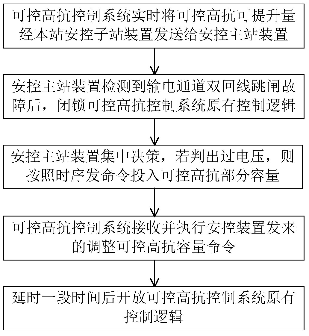
[0024] Such as figure 1 As shown, the present invention provides a coordinated control method with controllable high resistance, comprising the following steps:

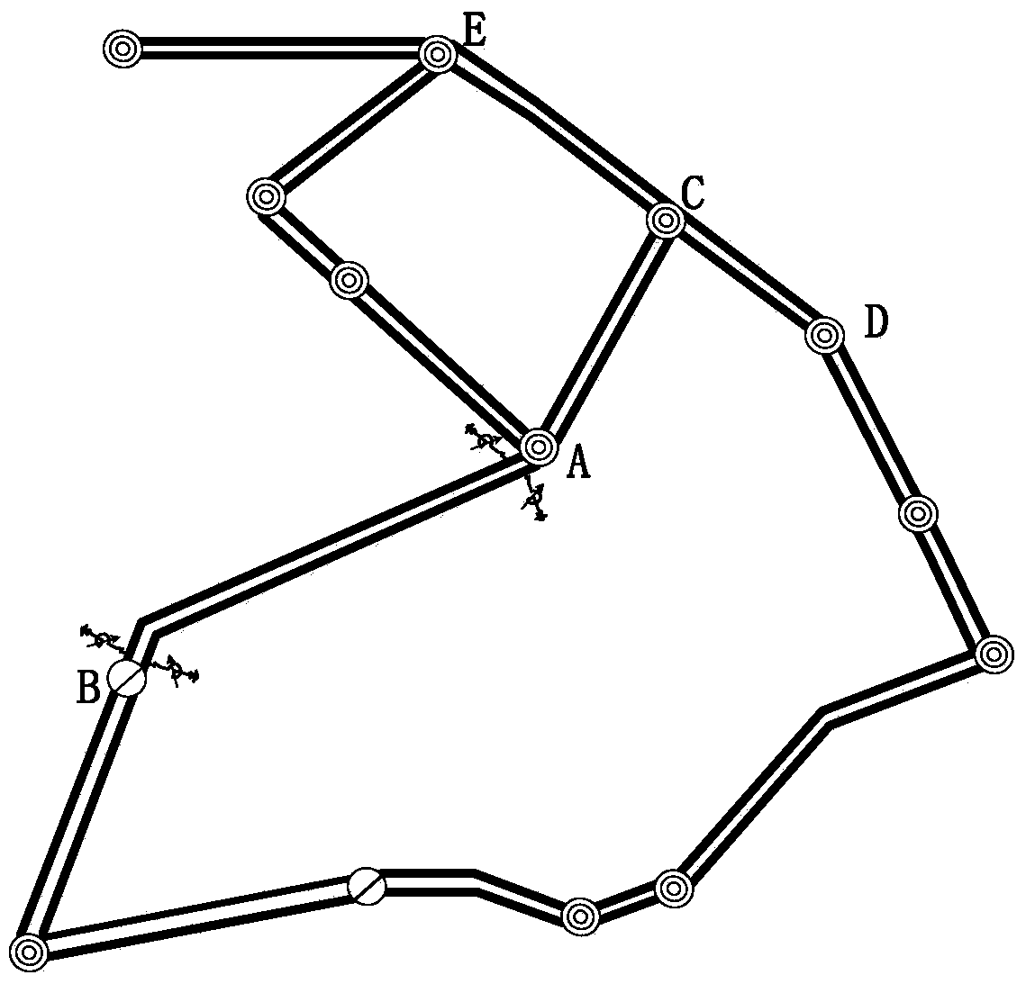
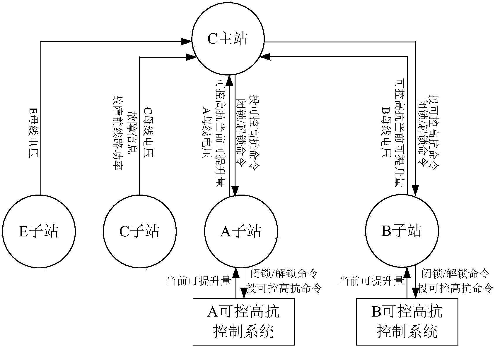
[0025] The controllable high-resistance control system described in step 1 in the figure sends the controllable high-resistance liftable amount to the safety control sub-station device in real time, and the safety control sub-station device sends the controllable high-resistance liftable amount to the security control master station device. to combine figure 2 Shown engineering application example of the present invention and image 3 As shown in the information exchange diagram of the present invention, two sets of controllable high resistance are installed at stations A and B as an example, and the controllable high resistance control systems of stations A and B send the amo...


PUM


Abstract

The invention discloses a method for coordination control of controllable shunt reactors. The method comprises the steps that a controllable shunt reactor control system submits the controllable shunt reactor lifting capacity to a master safety control station device through a home-station safety control substation device; when the master safety control station detects that line tripping occurs on a power transmission channel and the channel tide is larger than a certain value before the accident, the master safety control station sends information to the controllable shunt reactor control system through each safety control substation and locks the original control logic; the safety control substations collect the busbar voltage of each station after the accident and submit the voltages to the master safety control station, the master safety control station makes a decision in a centralized mode, and a command is given to put into part of capacity into the controllable shunt reactors according to the timing sequence if overvoltage is detected; the controllable shunt reactor control system receives and executes the command of adjusting the capacity; the original control logic of the controllable shunt reactor control system is open after a period of time. By the adoption of the method, coordination control of multiple sets of dynamic reactive power compensation equipment distributed in multiple transformer substations can be realized, overvoltage can be effectively restrained after the accident, and system voltage collapse caused by simultaneous incoordinate actions of multiple sets of controllable shunt reactors can be avoided.

Description

technical field [0001] The invention belongs to the field of power system control, and in particular relates to a method for realizing coordinated control and controllable high resistance by using a safety control device. Background technique [0002] The second link between Xinjiang Power Grid and the Northwest main grid was completed and put into operation in June 2013. So far, a 750 kV double-ring network with a total length of nearly 3,000 kilometers has been formed. The development of new energy (wind power, photovoltaic) in the area where the network channel is located presents the characteristics of large-scale, high concentration, and long-distance, and develops rapidly. With the large-scale access of new energy sources, large-scale and high-frequency fluctuations in wind power have caused frequent power flow fluctuations on the two channels connecting the Xinjiang Power Grid and the Northwest Main Grid, making it difficult to control reactive power and voltage. Con...

Claims


Application Information

Patent Timeline
Patent Type & Authority Applications(China)
IPC IPC(8): H02J3/16
CPCY02E40/34Y02E40/30
Inventor 王新宝夏彦辉常喜强
Owner NR ELECTRIC CO LTD
Why Eureka
Try Eureka