Peak closing method for reactive compensation capacitor bank

A technology for compensating capacitors and capacitor banks, which is applied in the field of peak closing to achieve the effect of suppressing inrush current and overvoltage and improving safety

Inactive Publication Date: 2015-02-25
SHANDONG UNIV OF TECH
View PDF4 Cites 2 Cited by
  • Summary
  • Abstract
  • Description
  • Claims
  • Application Information

AI Technical Summary

Problems solved by technology

[0003] When the reactive power of the grid is insufficient, the switching of the traditional reactive power compensation capacitor bank is random or at the voltage ze

Method used


Image

  • Peak closing method for reactive compensation capacitor bank
  • Peak closing method for reactive compensation capacitor bank
  • Peak closing method for reactive compensation capacitor bank

Examples


Embodiment Construction

[0012] The present invention will be further described below in conjunction with accompanying drawing:

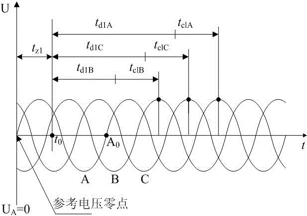
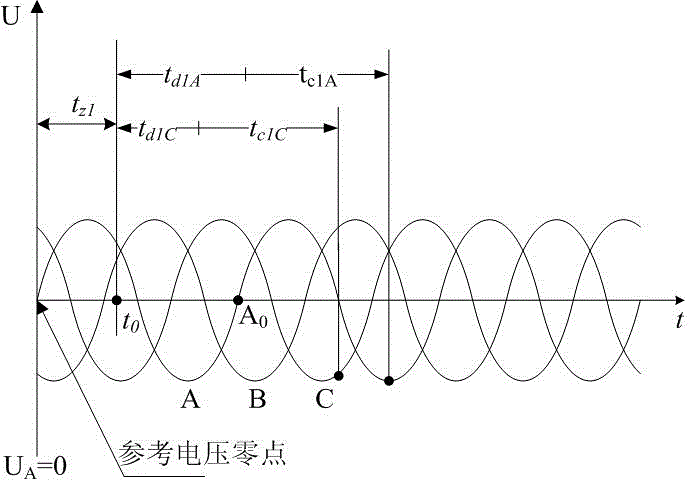
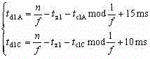
[0013] A peak closing method of a reactive power compensation capacitor bank. The reactive power compensation capacitor bank and the power grid system voltage are both closed when the voltage is at a peak value. Aiming at the star-shaped neutral point grounding and star-shaped neutral point ungrounded connection methods of parallel capacitor banks, Design the best closing phase of each phase capacitor bank separately;

[0014] The closing process of the star-shaped neutral point grounding capacitor bank can be equivalent to three independent single-phase circuits for analysis, by figure 1 It can be seen that in order to put the capacitor bank into operation as soon as possible and the inrush current caused by the closing time deviation is small, it is the best closing strategy to put the capacitor into operation at the peak voltage moment of each phase. When it is a refer...


PUM


Abstract

The invention provides a peak closing method for a reactive compensation capacitor bank and belongs to the field of power quality of electrical power systems. According to the peak closing method for the reactive compensation capacitor bank, the optimum closing phase positions of all phases of capacitor banks are designed according to the fact that the capacitor banks are connected in parallel in the mode that the star-shaped neutral points are grounded or not grounded, the minimum delay time required from the moment a closing signal is received to the moment the on-off action is triggered is calculated according to the intrinsic closing time of a switch and external factors, and thus the capacitor bank is applied to a power grid when both the value of the voltage of the capacitor bank and the value of the voltage of a power grid are peak values. Compared with other closing methods, the peak closing method for the reactive compensation capacitor bank has the advantages that the voltage change ratio is lowered under the same closing time deviation condition, rush current and overvoltage which are generated during closing of the capacitor bank are reduced, power quality is improved, and the peak closing method has an extremely good application prospect on the occasion that reactive compensation is conducted by means of the capacitor bank.

Description

technical field [0001] The invention provides a peak closing method of a reactive power compensation capacitor bank, which belongs to the field of electric energy quality of electric power systems. Background technique [0002] In the power system, the closing phase of the switch is usually random and uncertain, and a high-amplitude inrush current and overvoltage will be generated at the moment of closing the power equipment. The demand for power supply, with the continuous improvement of modern power electronics technology and switch manufacturing process, the switch is developing in the direction of intelligence; [0003] When the reactive power of the grid is insufficient, the switching of the traditional reactive power compensation capacitor bank is random or at the voltage zero crossing point. reach , although it has obvious advantages compared with random closing, inrush current and overvoltage will still be generated during the closing process of the capacitor. C...

Claims


Application Information

Patent Timeline
IPC IPC(8): H02J3/18
CPCY02E40/30H02J3/18
Inventor 杜钦君
Owner SHANDONG UNIV OF TECH
Why Eureka
Try Eureka