Power conversion device using matrix converter

A technology of power conversion device and frequency converter, which is applied in the direction of output power conversion device, AC power input conversion to AC power output, conversion equipment that can be converted to DC without intermediate conversion, etc., and can solve the problem of rising wiring inductance, etc. problem, to achieve the effect of suppressing overvoltage, realizing miniaturization, and canceling the snubber circuit

Inactive Publication Date: 2009-06-10
HITACHI LTD
View PDF11 Cites 4 Cited by
  • Summary
  • Abstract
  • Description
  • Claims
  • Application Information

AI Technical Summary

Problems solved by technology

However, when the wiring length between the capacitor of the LC filter and the switching part of the main circuit is too long, the inductance value of the wiring increases, and an overvoltage is generated on the switching element every time the switching element is turned ON / OFF

Method used


Image

  • Power conversion device using matrix converter
  • Power conversion device using matrix converter
  • Power conversion device using matrix converter

Examples


Embodiment Construction

[0034] The following reference Figure 1 to Figure 12 The implementation form of the first invention will be described.

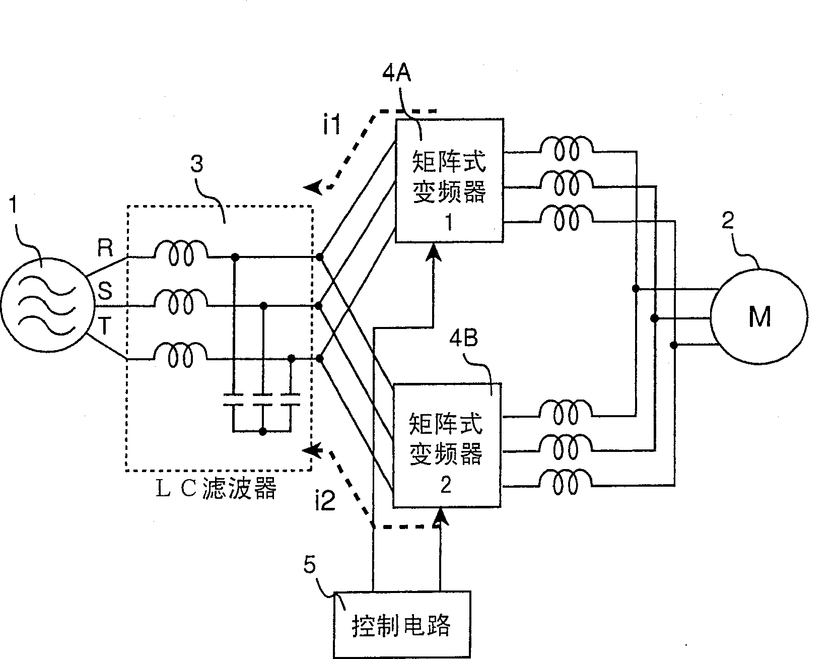
[0035] figure 1 It is a power conversion device using a matrix frequency converter according to the first embodiment of the present invention. The power conversion device consists of a commercial power source 1, a motor as a load 2, an LC filter 3, a matrix frequency converter 1 (4A), and a matrix frequency converter. The inverter 2 (4B) and the control circuit 5 for driving the matrix inverters 4A and 4B are constituted. In addition, i1 represents the current flowing into the LC filter 3 from the matrix inverter 1 (4A), and i2 represents the current flowing into the LC filter 3 from the matrix inverter 2 (4B). In the existing converter system, the commercial power source is first converted into direct current through a rectifier, and then converted into alternating current at any frequency through an inverter. At this time, in order to stabilize the direct c...


PUM


Abstract

There is provided a power conversion device using a matrix converter capable of reducing the size and weight of the LC filter which should be arranged at the input stage. N matrix converters are connected to a common LC filter. The N matrix converters operate a common load. In this case, a phase difference of the triangular wave signal (carrier signal) used for generating each matrix converter instruction value is set to 360 degrees / N and the common load is driven with the same frequency so that synchronized operation is performed. Thus, it is possible to obtain frequency of the current flowing into the LC filter which is the triangular wave signal(carrier signal) multiplied by N, thereby reducing the load on the LC filter.

Description

Technical field [0001] The invention relates to a power conversion device using a matrix frequency converter. The power conversion device directly converts AC power of a certain frequency into AC power of any frequency and outputs it. Background technique [0002] In the frequency converter used in the existing power conversion device, the rectifier part first converts the commercial power source into direct current, and then the inverter part converts the direct current into alternating current of any frequency and outputs it. In this conventional inverter, in order to reduce the pulsation, it is necessary to provide a smoothing capacitor in the DC part. In the prior art disclosed in Japanese Patent Laid-Open No. 3-261376, the triangular wave signal (carrier signal) used to generate the command value of the rectifier part is combined with the command value used to generate the inverter part. The phase of the triangular wave signal (carrier signal) is set to 0 degrees, and the sy...

Claims


Application Information

Patent Timeline
Patent Type & Authority Patents(China)
IPC IPC(8): H02M5/297H02M5/27
Inventor 绫野秀树稻叶博美大和育男大沼直人吉川敏文藤野笃哉
Owner HITACHI LTD
Why Eureka
Try Eureka