
Circuit arrangement for fast switching of converters

A circuit device and converter technology, applied in circuit devices, output power conversion devices, circuits, etc., can solve problems such as limiting the maximum switching frequency, and achieve the effect of high switching frequency and small wiring inductance

Active Publication Date: 2020-06-05
SIEMENS AG
View PDF4 Cites 0 Cited by
  • Summary
  • Abstract
  • Description
  • Claims
  • Application Information

AI Technical Summary

Problems solved by technology

[0003] The wiring inductance inside the module that occurs in this module technology limits the possible maximum switching frequency that can be used to switch the semiconductor switches

Method used


Image

  • Circuit arrangement for fast switching of converters
  • Circuit arrangement for fast switching of converters
  • Circuit arrangement for fast switching of converters

Examples


Embodiment Construction

[0025] The examples described below are preferred embodiments of the present invention. In these examples, the components of the described embodiments are correspondingly individual features of the invention which are considered independently of each other, which correspondingly also develop the invention independently of each other, whereby they can also be used individually or in combination with all Combinations different from the ones shown are considered to be part of the invention. Furthermore, the described embodiments can also be supplemented by further features of the invention already described.

[0026] In the figures, identical reference signs are assigned correspondingly to functionally identical elements.

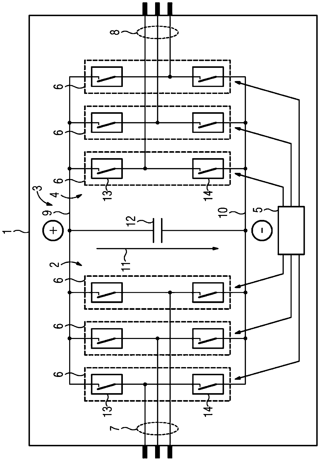
[0027] figure 1 A converter 1 is shown which comprises a rectifier 2 , a DC link circuit or short link 3 , an inverter 4 and a control device 5 . The rectifier 2 and the inverter 4 can each have a half-bridge 6 , through which the AC phase conductors or sim...


PUM


Abstract

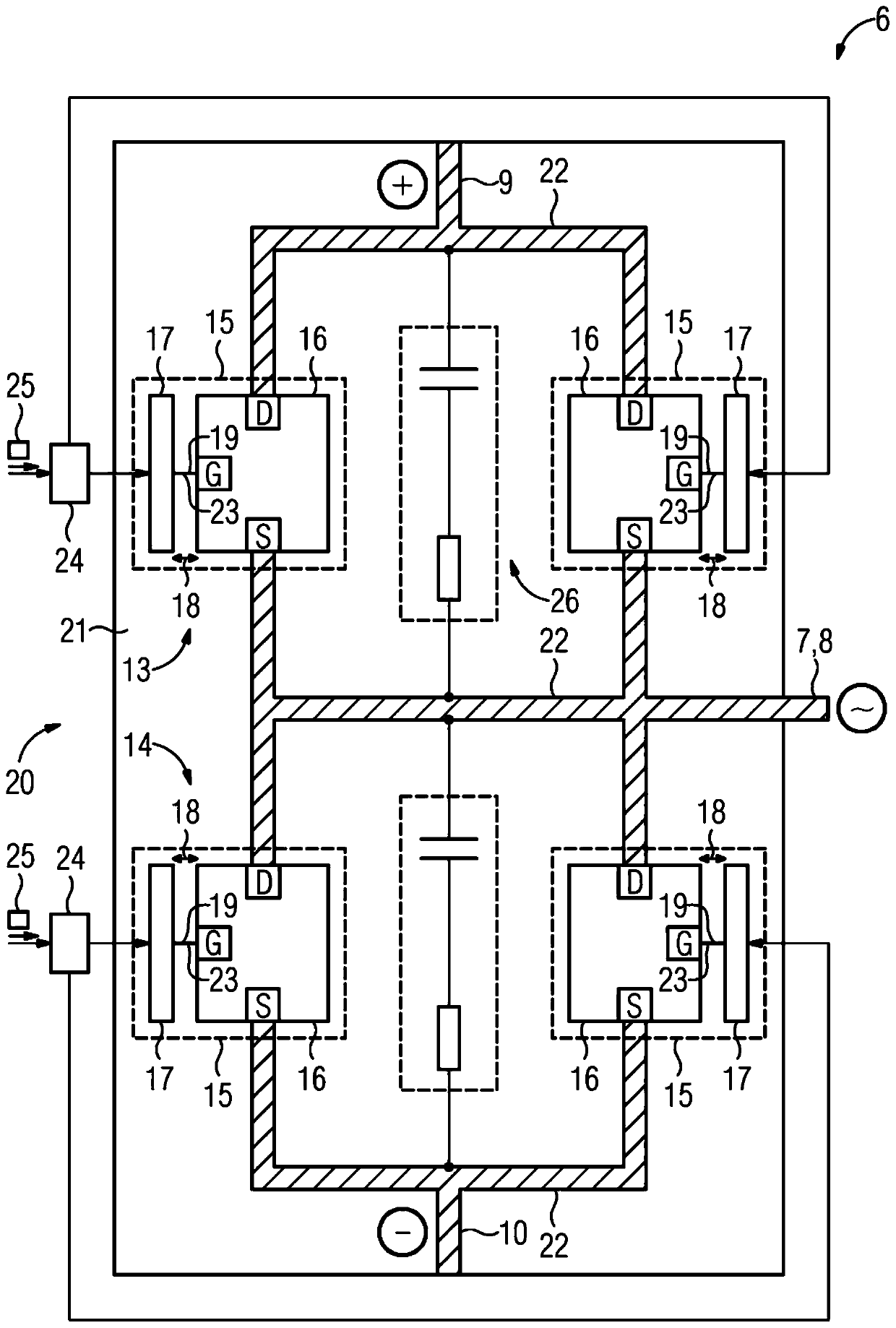
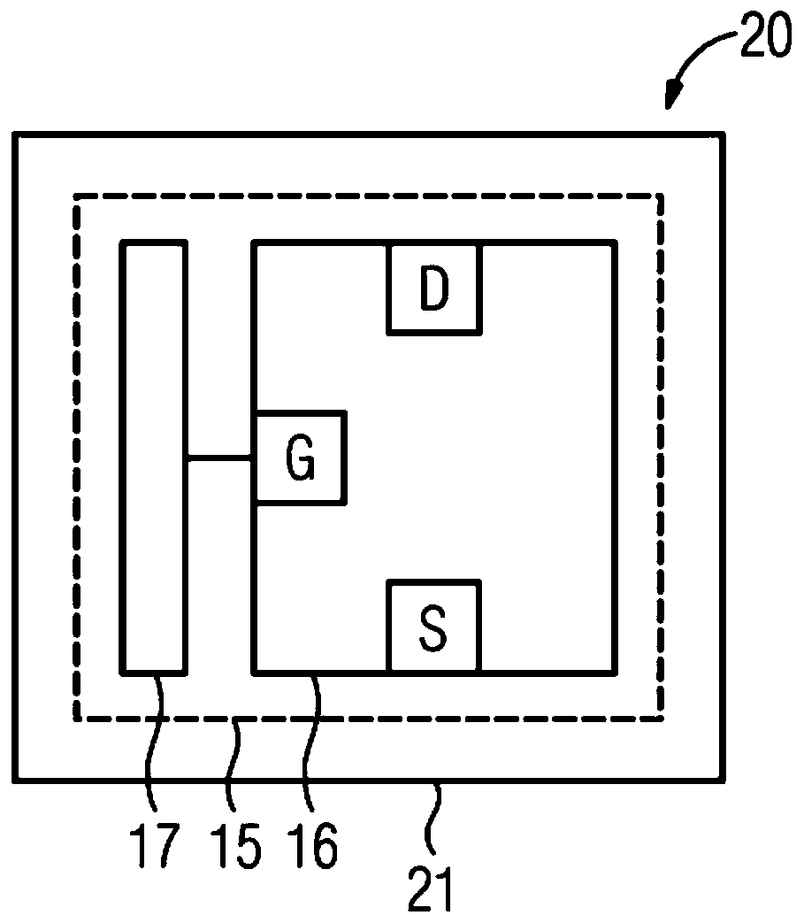
The invention relates to a circuit arrangement (20) for an electrical converter (1) having switching units (15), each of which has a semiconductor switch (16) and a gate for controlling the semiconductor switch (16) drive circuit (17). The semiconductor switch (17) should be able to be switched particularly quickly by its corresponding gate drive circuit (17). To this end, in each switching unit (15), the semiconductor switch (16) and the gate drive circuit (17) are arranged on a common carrier circuit board (21), and the gate drive circuit (17) is passed through At least one conductor track (23) of the carrier circuit board (21) is electrically connected to the gate (G) of the semiconductor switch (16).

Description

technical field [0001] The invention relates to a circuit arrangement for an electrical converter. The circuit arrangement has a plurality of switching units, each of which has a semiconductor switch and a gate driver circuit for controlling the semiconductor switch. An electrical converter having a circuit arrangement according to the invention also belongs to the invention. Background technique [0002] In a converter for power electronics, the rectifier of the converter and / or the semiconductor switches of the inverter can be provided as modules. Such a module then has, for example, three half-bridges formed by semiconductor switches. To control the semiconductor switches, the module is connected to a separate circuit board on which the gate drive circuits of the semiconductor switches are implemented. The board is connected to the module at the control inputs by wires. Inside the module, the control input is connected to the gate of the semiconductor switch through b...

Claims


Application Information

Patent Timeline
Patent Type & Authority Patents(China)
IPC IPC(8): H02M7/00H02M1/088
CPCH02M1/088H02M7/003H02K11/33H01L29/1608H01L29/2003H03K17/161H03K17/687H05K1/0237H05K2201/10166
Inventor M.布卢姆M.芬肯泽勒W.基弗T.科马M.波布尔
Owner SIEMENS AG
Learn More