Power shifter for railway vehicle

A technology for a power conversion device and a railway vehicle, which is applied in vehicle components, conversion equipment for intermediate conversion to DC conversion, and applications, can solve problems such as reducing inductance, and achieve the effects of reducing wiring inductance and improving maintainability.

Inactive Publication Date: 2005-08-17
KK TOSHIBA
View PDF1 Cites 1 Cited by
  • Summary
  • Abstract
  • Description
  • Claims
  • Application Information

AI Technical Summary

Problems solved by technology

There is a phenomenon that the current between the converter unit 13 and the inverter unit 15 vibrates due to the inductance of the partial wiring of the DC connection conductor 22, and it is necessary to increase the cross-sectional area of ​​the DC connection conductor 22 or the like, or make it thinner. , or overlap, etc. to seek to reduce the inductance

Method used


Image

  • Power shifter for railway vehicle
  • Power shifter for railway vehicle
  • Power shifter for railway vehicle

Examples


Embodiment Construction

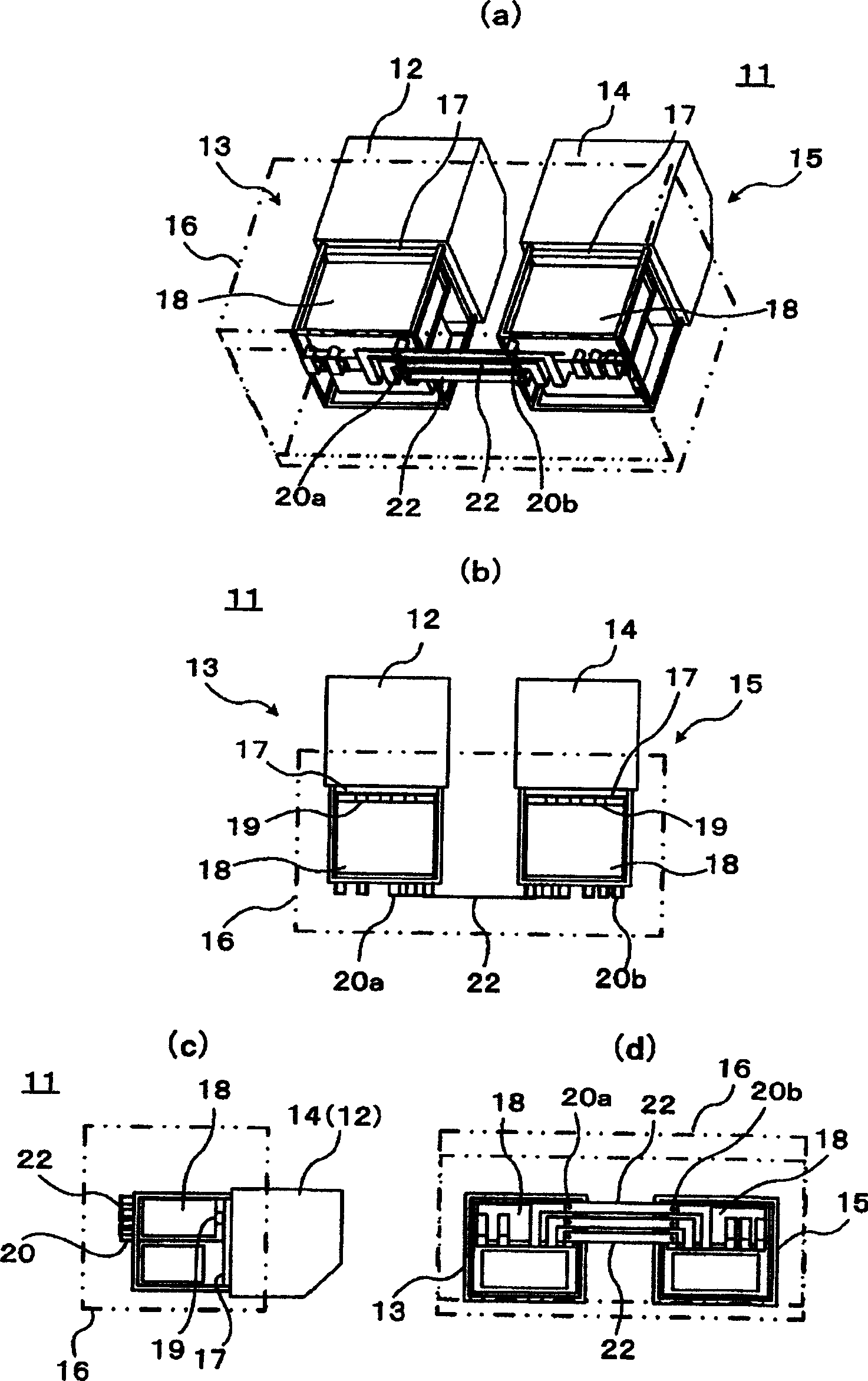
[0025] figure 1 is a structural diagram showing a power conversion device for railway vehicles according to the first embodiment of the present invention, wherein figure 1 (a) is an oblique view, figure 1 (b) is a floor plan, figure 1 (c) is a side view, figure 1 (d) is the back view. This first embodiment is relative to Figure 6 According to the prior art shown, on the side of the inverter unit 15 located on the rear side of the converter unit 13 there is an external connection of the converter unit with a DC output for connection to the terminal 19 of the smoothing capacitor 18 The terminal 20a is provided with the inverter unit external connection terminal 20b for connecting with the terminal 19 of the smoothing capacitor 18 on the side of the converter unit 13 located on the back side of the inverter unit 15, so as to pass the DC input. The connection conductor 22 connects 20a and 20b. and Figure 6 The same symbols are used for the same elements, and their repe...


PUM


Abstract

The present invention provides a camera shooting method and a camera shooting apparatus which are capable of realizing the manipulation sense desirable for users and realizing the maneuverability satisfying user requirement, the present invention also provides a program for executing the method and a storage medium for storing the program, wherein, the service speed variable quantity of an operational unit which is arranged into concentric circle shape relative to a light axis of an optical system is detected, and the actuating speed of the optical system is determined according to the detection results of the variable quantity by making use of the detection results of the variable quantity used for determining the detection module and the relevancy variable quantity of the remotion of the optical system.

Description

technical field [0001] The present invention relates to a power conversion device for railway vehicles used in AC railway vehicles powered by AC overhead wires. Background technique [0002] The power conversion device for railway vehicles is installed under the chassis of the railway vehicle, and the AC is converted into DC by the converter circuit, and the DC converted by the converter circuit is converted into AC by the inverter circuit, which is used to drive the railway vehicle power supply of the motor. [0003] Figure 6 is a structural diagram of a conventional power conversion device for railway vehicles, Figure 6 (a) is an oblique view, Figure 6 (b) is a floor plan, Figure 6 (c) is a side view, and Figure 6 (d) is the back view. The power conversion device 11 for the railway vehicle is installed under the chassis of the railway vehicle, and the converter unit 13 containing the converter circuit 12 and the inverter unit 15 containing the inverter circuit 14 are...

Claims


Application Information

Patent Timeline
IPC IPC(8): B60L15/00B60L9/24H02M5/40
CPCY02T10/7241Y02T10/72B60L9/24B60L50/51B60L2200/26B60L2210/30B60L2210/40B60Y2200/30
Inventor 桥本隆黑泽悟
Owner KK TOSHIBA
Why Eureka
Try Eureka