Image forming apparatus

a technology of image forming and forming parts, which is applied in the direction of instruments, static indicating devices, optical elements, etc., can solve the problems of difficult for a person to guide a person to the store, and difficult for a person to recognize the presence and content of images, etc., to achieve the effect of increasing the rang

Inactive Publication Date: 2011-08-25
SEIKO EPSON CORP
View PDF4 Cites 39 Cited by
  • Summary
  • Abstract
  • Description
  • Claims
  • Application Information

AI Technical Summary

Benefits of technology

[0009]An advantage of some aspects of the invention is to provide an image forming apparatus that can allow even a moving person to easily recognize the presence and the content of an image and can guide a target person to a desired point (a guiding point).

Problems solved by technology

Therefore, it is difficult for a person to recognize the presence and the content of the image.
Therefore, it is difficult for the person to recognize the presence and the content of the image.
When a setting position of the screen is relatively distant from the store (a point to which the store desires to guide a person), even if it is possible to allow the person to recognize the presence and the content of the image, it is difficult to guide the person to the store.
Therefore, effects of the advertisement (appeal effects) cannot be sufficiently obtained.

Method used


Image

  • Image forming apparatus
  • Image forming apparatus
  • Image forming apparatus

Examples


first embodiment

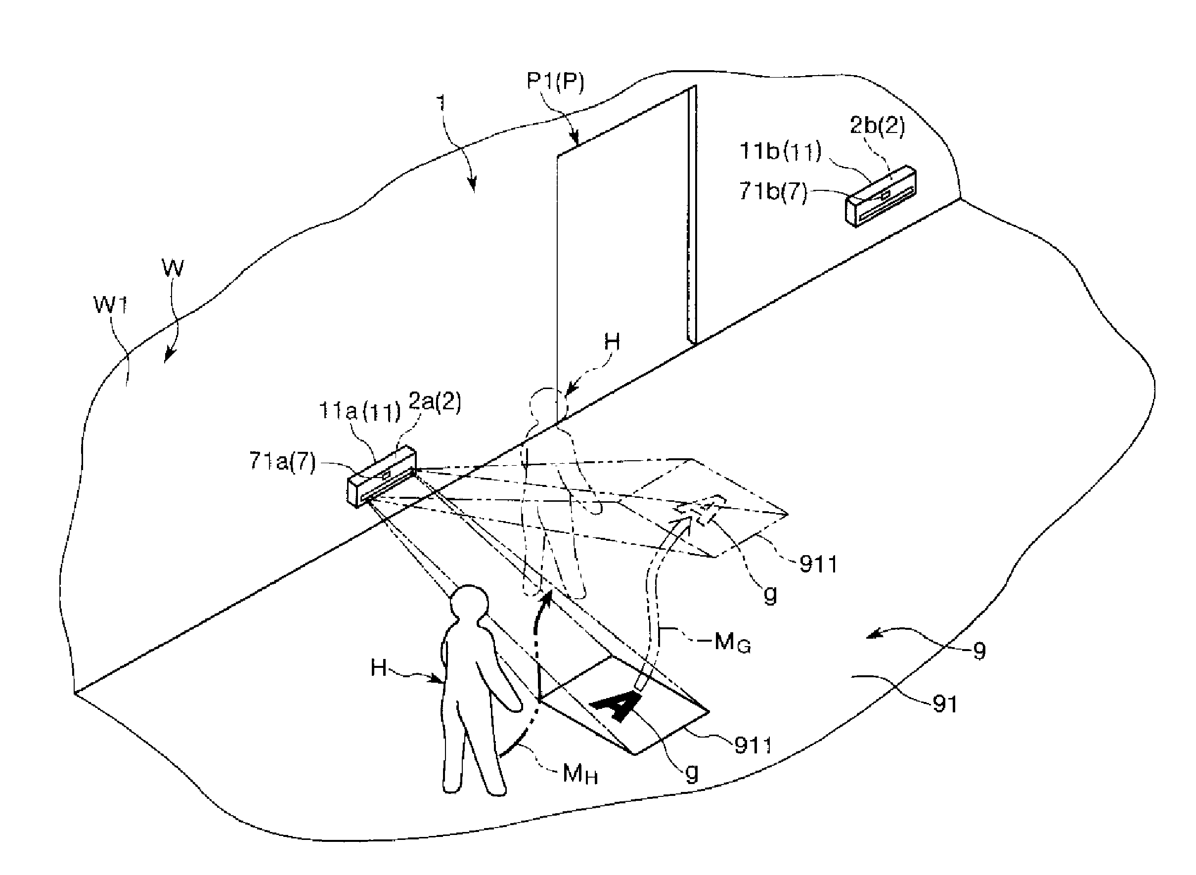
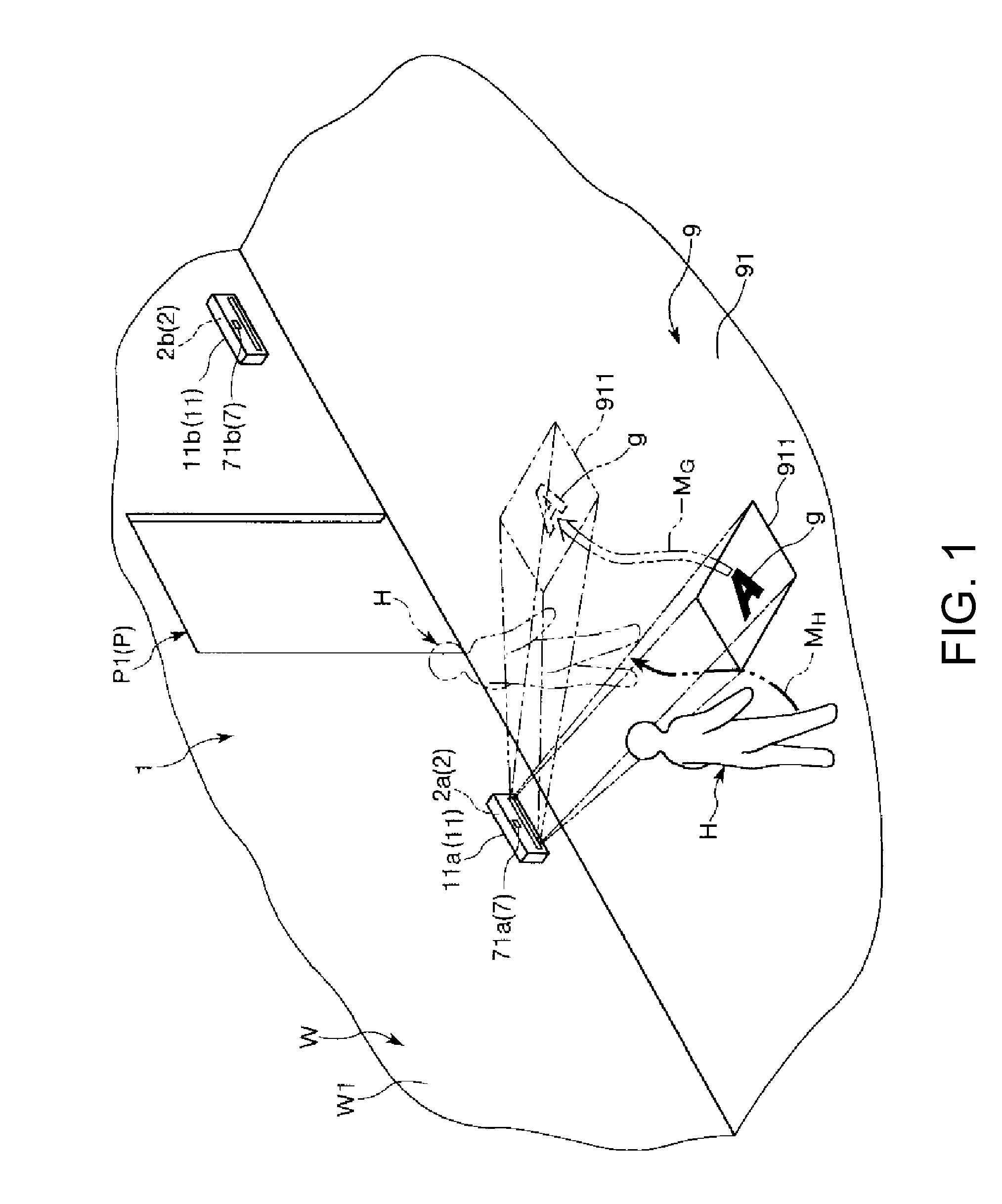
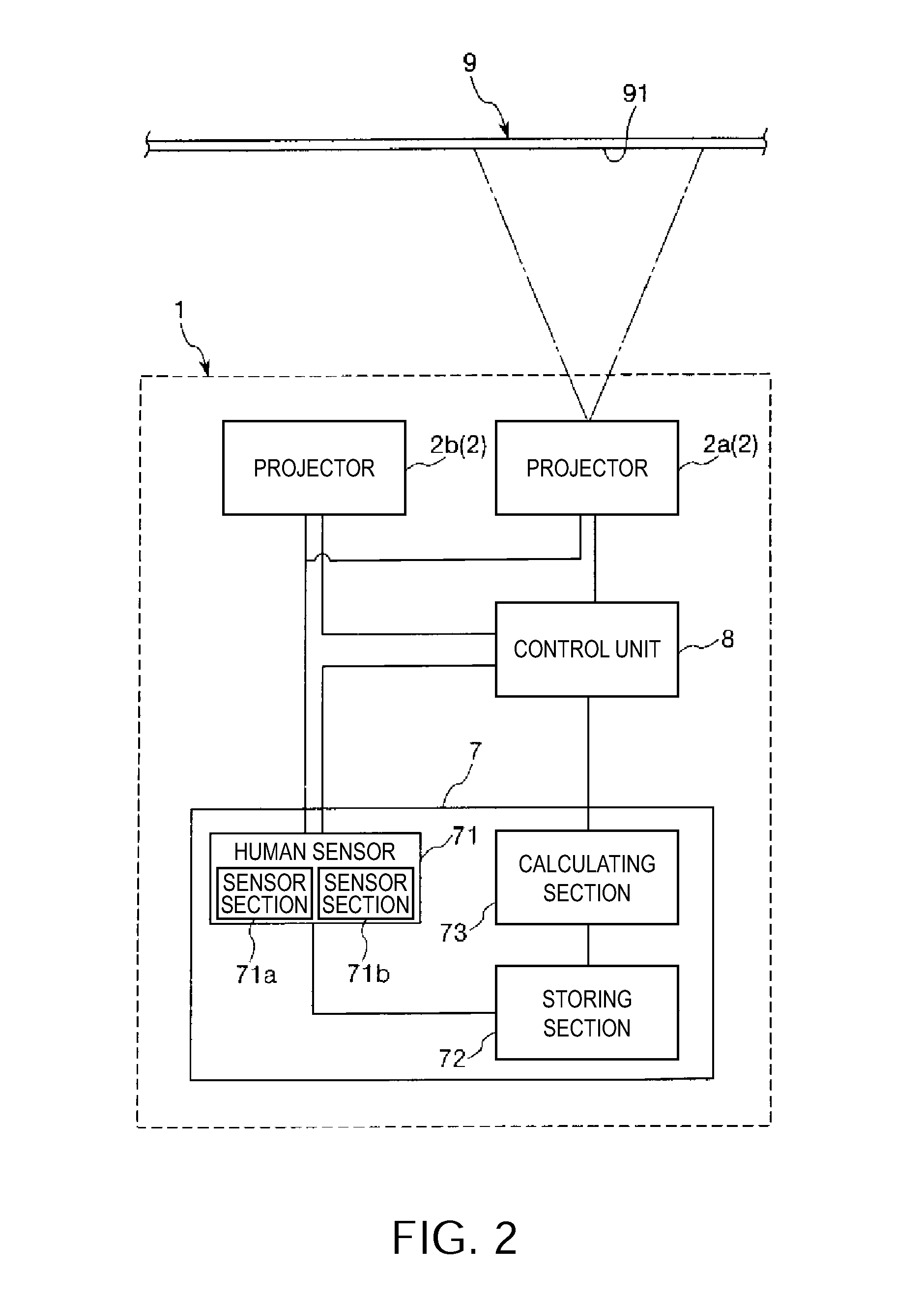
[0068]FIG. 1 is a diagram showing an image forming apparatus according to a first embodiment of the invention. FIG. 2 is a block diagram showing a schematic configuration of the image forming apparatus shown in FIG. 1. FIG. 3 is a diagram showing a schematic configuration of a projector included in the image forming apparatus shown in FIG. 2. FIG. 4 is a partial sectional perspective view of an optical scanner included in the projector shown in FIG. 3. FIGS. 5A and 5B are sectional views for explaining the operation of the optical scanner shown in FIG. 4. FIG. 6 is a block diagram showing a control system (an actuation control unit, a light scanning unit, and a light source unit) of the projector shown in FIG. 3. FIG. 7A is a side view for explaining the operation of the projector shown in FIG. 3. FIG. 7B is a front view for explaining the operation of the projector shown in FIG. 3. FIG. 8 is a graph showing transition of a deflecting angle (a change with time of the deflecting angl...

second embodiment

[0257]An image forming apparatus according to a second embodiment of the invention is explained below.

[0258]FIG. 19 is a schematic plan view showing an optical scanner of a projector included in the image forming apparatus according to the second embodiment of the invention. FIG. 20 is a sectional view taken along line B-B shown in FIG. 19. FIG. 21 is a block diagram showing a voltage applying unit of a driving unit included in the optical scanner shown in FIG. 19. FIGS. 22A and 22B are diagrams showing an example of voltages generated by a first voltage generating section and a second voltage generating section included in the voltage applying unit shown in FIG. 21. FIG. 23A is a side view for explaining the operation of the projector included in the image forming apparatus according to the second embodiment of the invention. FIG. 23B is a front view for explaining the operation of the projector included in the image forming apparatus according to the second embodiment of the inven...

third embodiment

[0300]An image forming apparatus according to a third embodiment of the invention is explained below.

[0301]FIG. 24 is a diagram showing the image forming apparatus according to the third embodiment of the invention.

[0302]Concerning the image forming apparatus according to the third embodiment, differences from the image forming apparatuses according to the first and second embodiments are mainly explained below. Explanation of similarities is omitted.

[0303]The image forming apparatus according to the third embodiment is substantially the same as the image forming apparatus according to the first embodiment except that the arrangement of a display surface on which an image is displayed and the image forming apparatus is different. In FIG. 24, components same as those in the embodiments explained above are denoted by the same reference numerals and signs.

[0304]As shown in FIG. 24, in an image forming apparatus 1A, the display surface 91 is set on a ceiling surface C1 of a ceiling C. S...


PUM


Abstract

An image forming apparatus includes: a projector configured to be capable of projecting light to thereby display an image on a rendering region formed on a display surface set around a guiding point to which a person should be guided and changing a position of the rendering region; a detecting unit that detects whether a person is present in a detection region set near the display surface and detects, when a person is present in the detection region, a moving state of the person; and a control unit that controls, on the basis of a detection result of the detecting unit, driving of the projector to guide the person present in the detection region to the guiding point.

Description

BACKGROUND[0001]1. Technical Field[0002]The present invention relates to an image forming apparatus.[0003]2. Related Art[0004]A projector is known as an apparatus that projects light on the surface of an object such as a screen and displays a desired image on a projection surface of the screen. As such a projector, a projector including an optical scanner that one-dimensionally or two-dimensionally scans light is put to practical use (see, for example, JP-A-2008-116668 (Patent Document 1)).[0005]The projector disclosed in Patent Document 1 includes a first optical scanner in which a movable plate having a light reflecting section pivots around an x axis, a second optical scanner in which a movable plate having a light reflecting section pivots around a y axis orthogonal to the x axis, and a light source device that emits light such as a laser. Such a projector scans light emitted from the light source device with the first optical scanner and further scans the scanned light with the...

Claims


Application Information

Patent Timeline
Patent Type & Authority Applications(United States)
IPC IPC(8): G03B21/14
CPCG02B26/101G02B27/0093G03B21/14G03B33/06G09G2310/0232G09G2354/00H04N9/3129H04N9/3194G09G3/025
Inventor WAKABAYASHI, SHUICHINAKAMURA, NORIOMIZOGUCHI, YASUSHI
Owner SEIKO EPSON CORP
Why Eureka
Try Eureka