Power Factor Corrected Switched Mode Power Supply
Active Publication Date: 2011-08-25
EATON INTELLIGENT POWER LIMITED
View PDF5 Cites 8 Cited by
- Summary
- Abstract
- Description
- Claims
- Application Information
AI Technical Summary
Problems solved by technology
When the switches of a power factor corrected switched mode power supply are switched at a constant frequency there is a significant EMI noise signature at certain frequencies.
The problem with this approach is that the rate of change of the switching frequency is minimized at the point of maximum power transfer and so much of the EMI noise power is confined to a narrow range.
Method used
View moreImage
Smart ImageViewing Examples
Examples
first embodiment
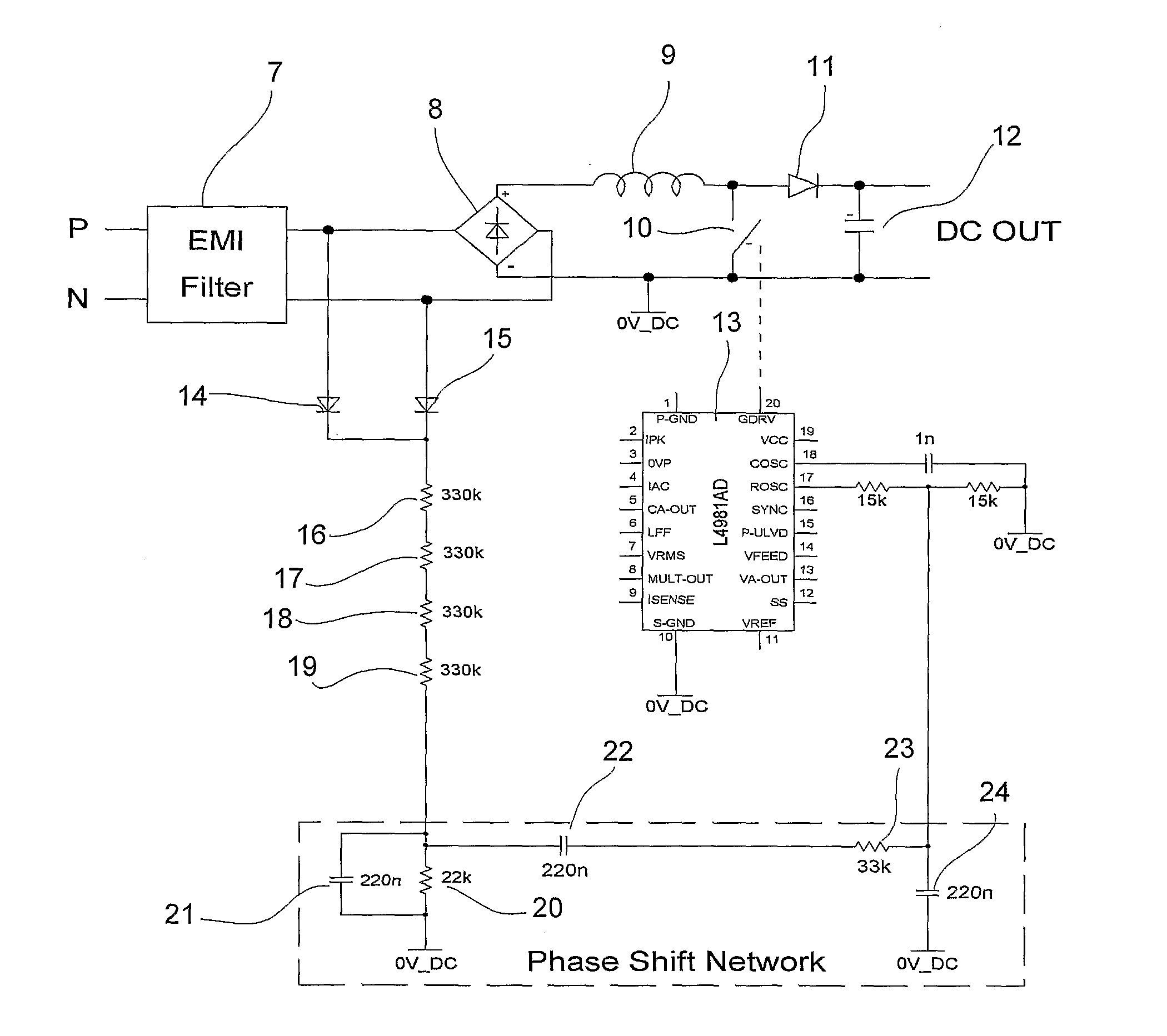
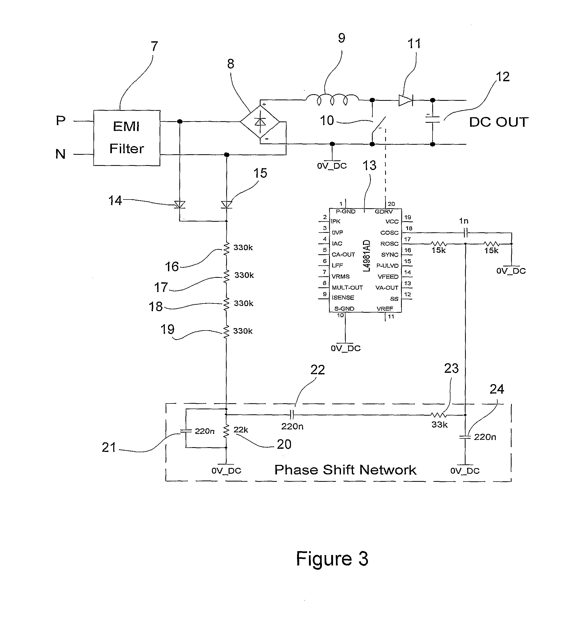
[0017]FIG. 3 shows a power factor corrected switched mode power supply according to a
second embodiment
[0018]FIG. 4 shows a power factor corrected switched mode power supply according to a
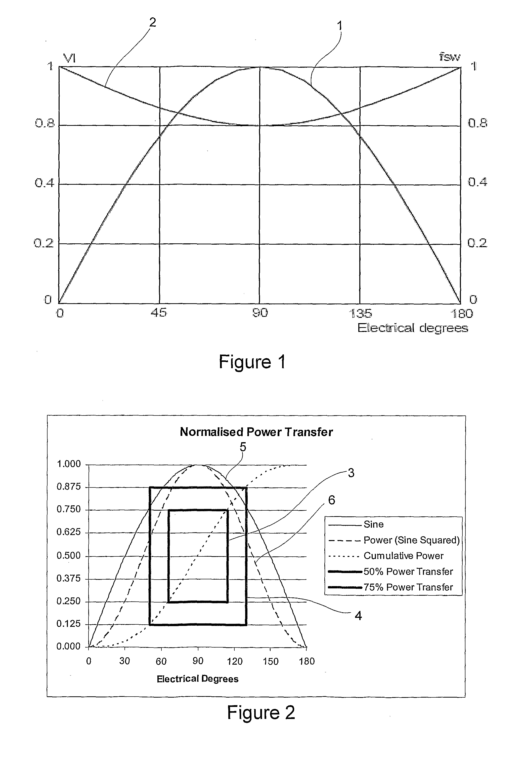
[0019]FIG. 5 illustrate the operation of the power factor corrected switched mode power supply of FIG. 3.
Login to View More PUM
Abstract
A power factor corrected switched mode power supply including a phase shifter that senses the mains frequency and phase shifts it to produce a phase shifted signal which modulates the switching signal supplied to the switches based on the phase shifted signal. The rate of change of the frequency of the switching signal may be controlled to be greatest in regions of greatest power transfer.
Description
FIELD OF THE INVENTION[0001]This invention relates to a power factor corrected switched mode power supply having reduced electro-magnetic interference (EMI) noise.BACKGROUND OF THE INVENTION[0002]When the switches of a power factor corrected switched mode power supply are switched at a constant frequency there is a significant EMI noise signature at certain frequencies. It is known to modulate the switching frequency applied to the switches to spread the noise spectrum over a wider range. When compared to an un-modulated switching frequency, this reduces the average noise energy.[0003]FIG. 1 shows a prior art approach to modulating the switching frequency based on the phase of the rectified power supply (as per the application note AN833 for the L4981B integrated circuit produced by STMicroelectronics). Curve 1 shows the mains waveform and line 2 the switching frequency modulation. As shown in FIG. 1 the switching frequency is reduced to 80% at the point of maximum power transfer an...
Claims
Login to View More Application Information
Patent Timeline
IPC IPC(8): H02M7/06
CPCH02M1/4225Y02B70/126H02M1/44Y02B70/10Y02P80/10H02M1/42
Inventor HUNGER, PHILLIP
Owner EATON INTELLIGENT POWER LIMITED
- R&D Engineer
- R&D Manager
- IP Professional
Why Eureka
- Industry Leading Data Capabilities
- Powerful AI technology
- Patent DNA Extraction
Eureka Blog
Learn More Browse by: Latest US Patents, China's latest patents, Technical Efficacy Thesaurus, Application Domain, Technology Topic, Popular Technical Reports.
© 2024 PatSnap. All rights reserved.Legal|Privacy policy|Modern Slavery Act Transparency Statement|Sitemap|About US| Contact US: help@patsnap.com