Power supply with integrated bridge and boost circuit
a power supply and boost circuit technology, applied in the direction of electric variable regulation, process and machine control, instruments, etc., can solve the problems of increasing the efficiency of their power supply, reducing the size, and avoiding the forward power loss of diodes
- Summary
- Abstract
- Description
- Claims
- Application Information
AI Technical Summary
Benefits of technology
Problems solved by technology
Method used
Image
Examples
Embodiment Construction
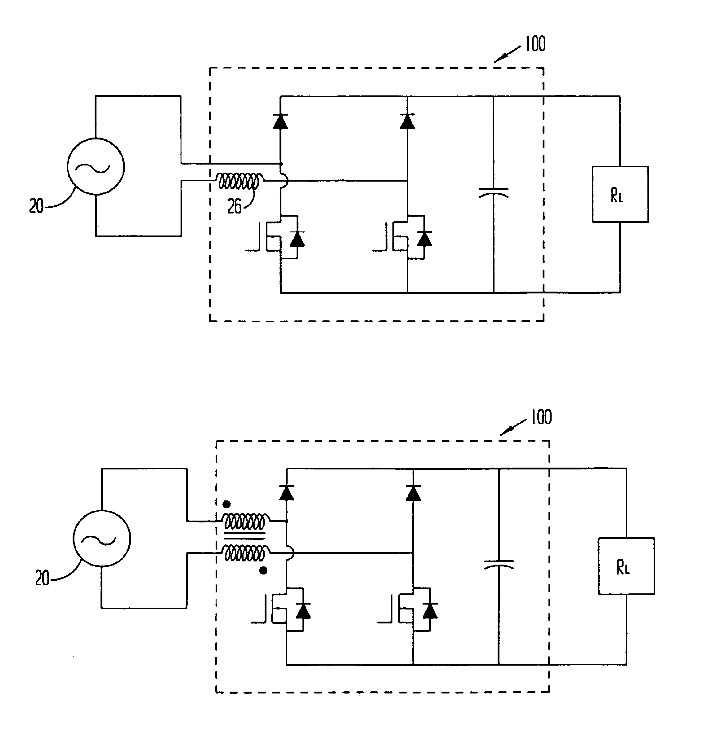
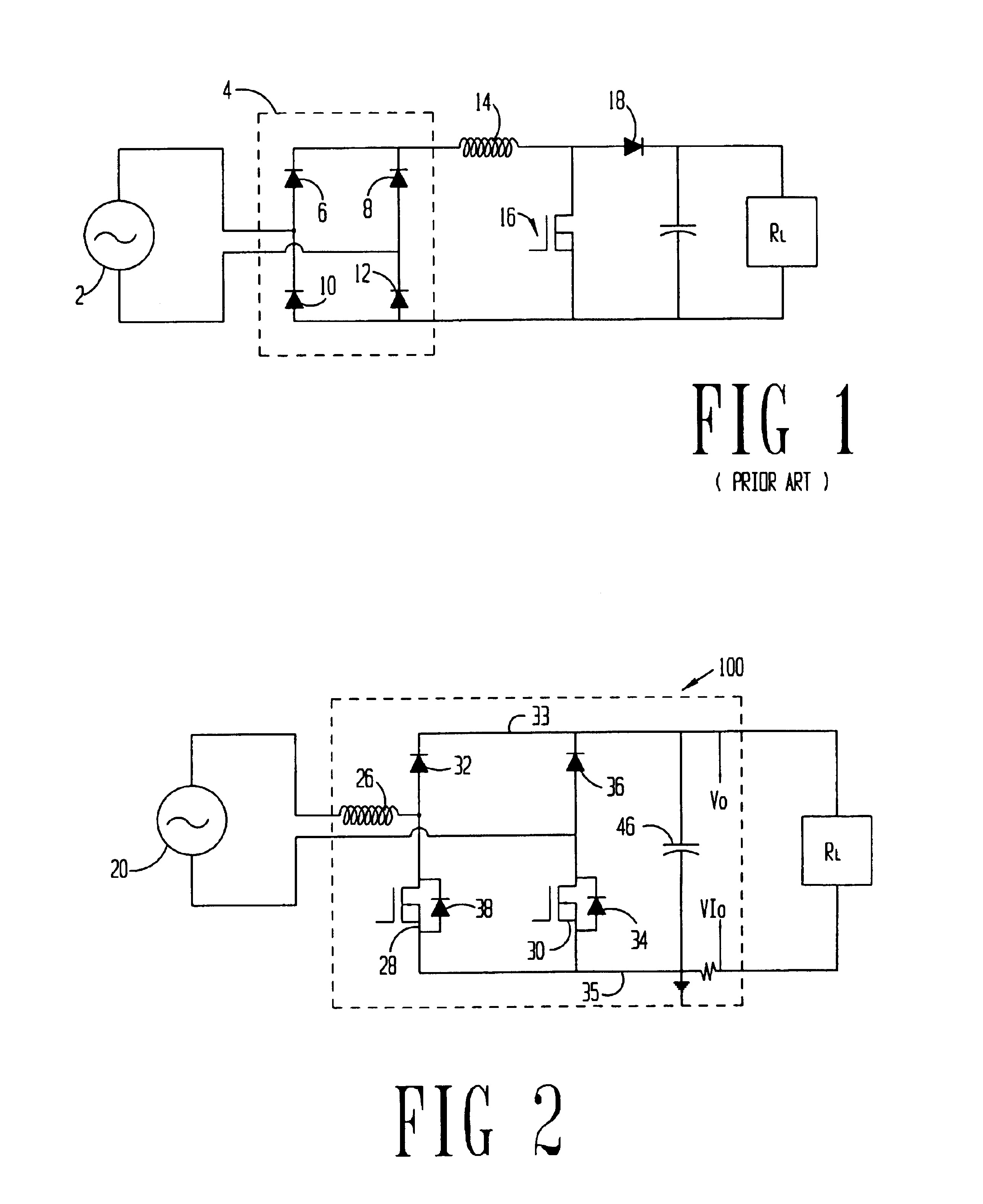
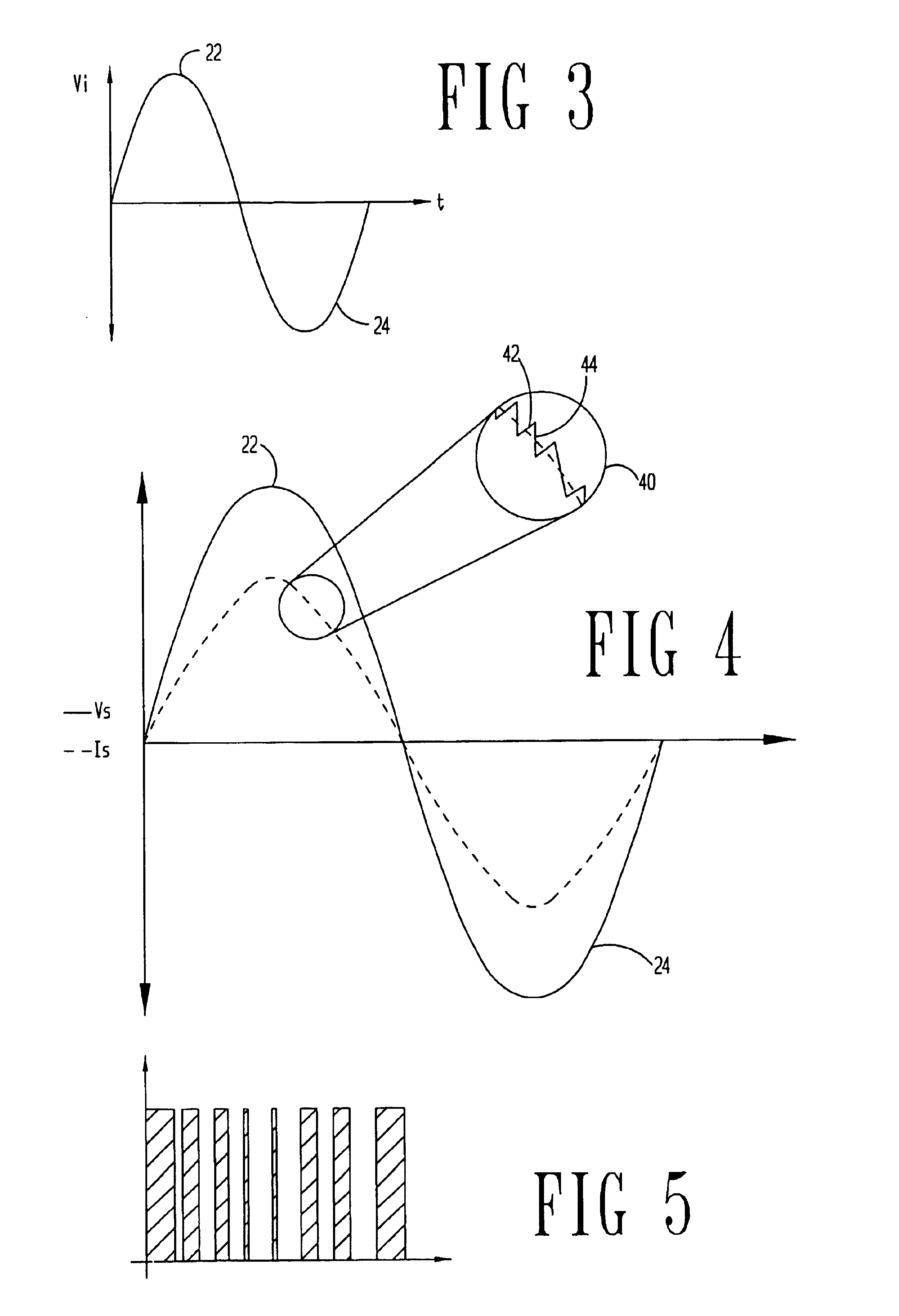
The problems noted above are solved in large part by an integrated bridge and boost circuit for a power conversion unit. More particularly, in the preferred embodiments, the inductor is coupled between the alternating current (AC) source and a rectifying bridge topology where at least two of the diodes are shunted with switch devices, which switch devices in the preferred embodiments are field effect transistors (FETs). Charging cycles of the inductor in either the positive or negative half cycle of the source voltage take place with current flowing through the inductor and back to the source through two FETs. The conduction power loss associated with the two FETs is significantly less than the power loss associated with the two diodes and boost switch experienced in the related art charging cycle. During the discharge cycle of the inductor, the current flow experiences the forward power loss associated with two power diodes, rather than the three diode forward power loss associated...
PUM
 Abstract
Description
Claims
Application Information
 - R&D
- Intellectual Property
- Life Sciences
- Materials
- Tech Scout
- Unparalleled Data Quality
- Higher Quality Content
- 60% Fewer Hallucinations
Browse by: Latest US Patents, China's latest patents, Technical Efficacy Thesaurus, Application Domain, Technology Topic, Popular Technical Reports.
© 2025 PatSnap. All rights reserved.Legal|Privacy policy|Modern Slavery Act Transparency Statement|Sitemap|About US| Contact US: help@patsnap.com


