AC LED lamp involving an LED string having separately shortable sections

a technology of led string and led lamp, which is applied in the direction of electric light circuit arrangement, electroluminescent light source, electric apparatus, etc., can solve the problems of one watt resistive power loss for a four watt led lamp, power loss, and lower efficiency of led lamp and heat generation, so as to prevent electrolytic capacitor failure, reduce component count, and improve lamp reliability.

Active Publication Date: 2011-09-22
ACTIVE SEMI
View PDF24 Cites 100 Cited by
  • Summary
  • Abstract
  • Description
  • Claims
  • Application Information

AI Technical Summary

Benefits of technology

[0011]In the AC LED lamp, the number of LEDs conducting current and the LED string current flow are controlled and regulated to provide superior efficiency, reliability, anti-flicker, regulation against line voltage variations, power factor correction, lamp over-voltage protection, lamp over-current protection, and lamp over-temperature protection. Employing the disclosed lamp architecture allows a high-efficiency solid-state AC LED lamp to be realized that involves no electrolytic capacitor and that only involves a relatively small number of components. Avoiding the use of an electrolytic capacitor prevents electrolytic capacitor failures that may otherwise degrade reliability if electrolytic capacitors were included in the AC LED lamp. The reduced component count improves lamp reliability and extends the mean time to failure of the lamp. Electromagnetic Interference (EMI) issues are minimized as compared to many AC-to-DC converter LED lamps because the novel AC LED lamp described here does not involve high frequency power switching.

Problems solved by technology

A disadvantage of the current-limiting resistor approach is power loss.
This power loss results in lower efficiency of the LED lamp and higher heat generation.
This results in one watt of resistive power loss for a four watt LED lamp.
This amounts to a twenty-six percent loss of efficiency.
This results in one watt of resistive power loss for a four watt LED lamp.
This amounts to a twenty-six percent loss of efficiency.
This increase in LED current causes seventy percent more power loss across the resistances, causes increased heat dissipation, and causes a roughly fifty percent increase in power consumption.
A disadvantage of this approach is the need to provide a high value capacitor.
Another disadvantage is its reliance on a stable dV / dt and its general incompatibility with triac dimming.
Such a circuit can be driven with a high frequency AC source controller, but doing so requires complicated circuitry for the high frequency driver.

Method used


Image

  • AC LED lamp involving an LED string having separately shortable sections
  • AC LED lamp involving an LED string having separately shortable sections
  • AC LED lamp involving an LED string having separately shortable sections

Examples


first embodiment

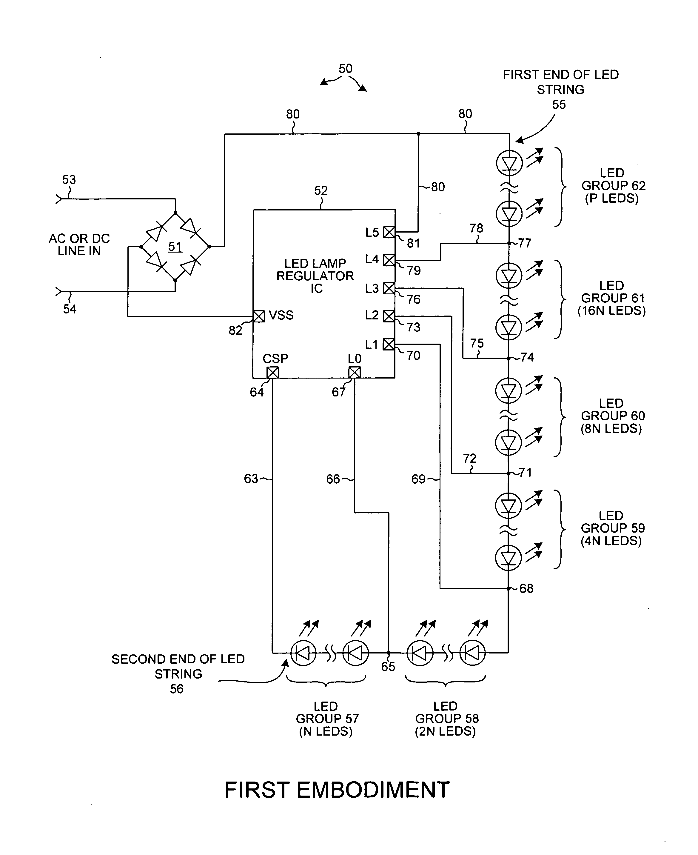
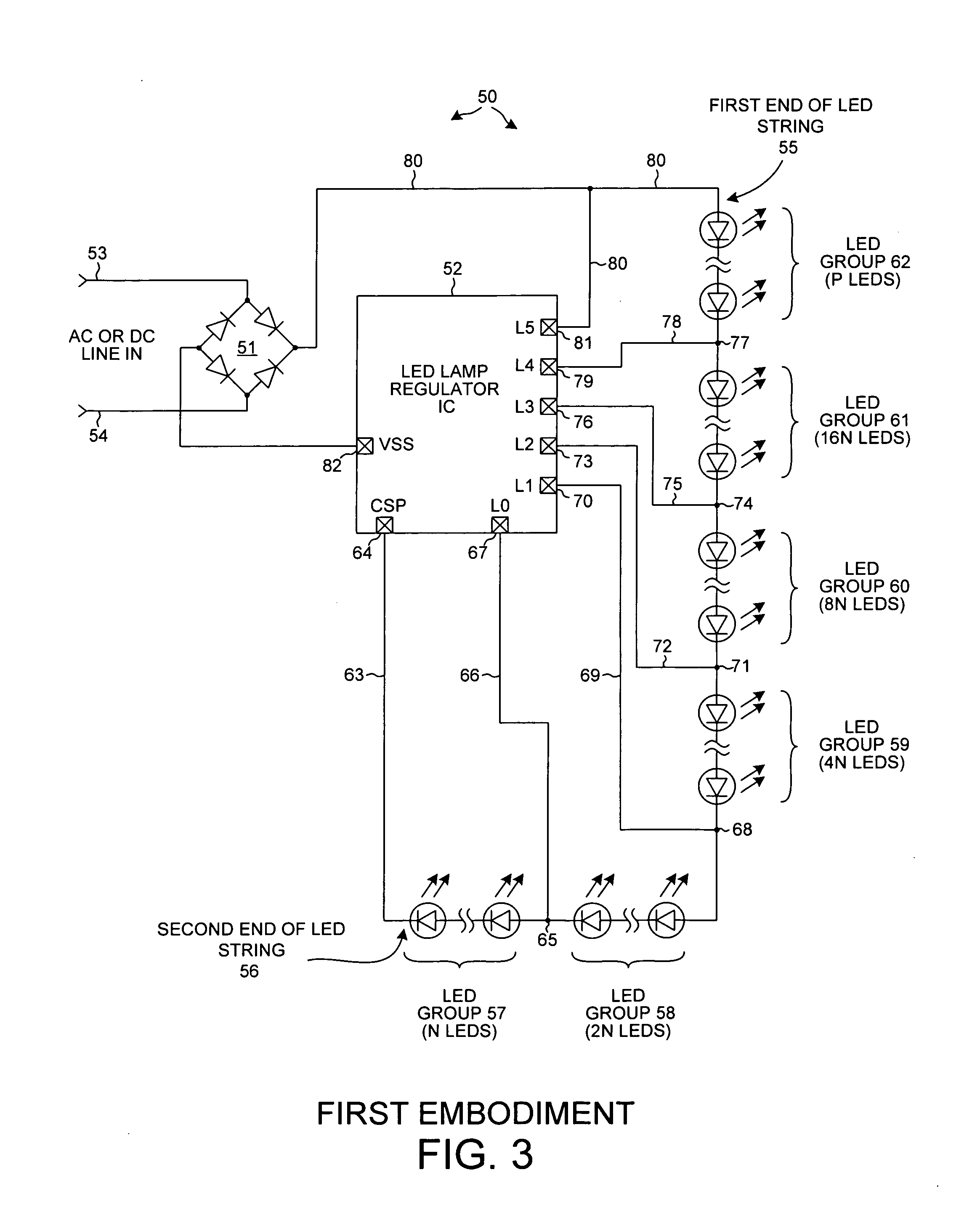
[0034]FIG. 3 is a circuit diagram of an AC LED lamp 50 in accordance with a The AC LED lamp 50 includes a full-wave rectifier 51, an LED lamp regulator integrated circuit (also referred to as a control integrated circuit) 52, and a string of series-connected LEDs. Rectifier 51 is connected to input power terminals 53 and 54 as illustrated. Either an AC or a DC line-in input power signal is received on terminals 53 and 54.

[0035]The LED string has a first end 55 and a second end 56. The LED string in turn includes several sections 57-62. A section is also referred to here as a group of LEDs. The illustrated nodes between the various LED groups are referred to here loosely in a non-technical sense as interconnection nodes. As illustrated in FIG. 3 second end 55 of the LED string is coupled via a conductor 63 to CSP terminal 64; interconnection node 65 of the LED string is coupled via a conductor 66 to L0 terminal 67 of integrated circuit 52; interconnection node 68 of the LED string i...

second embodiment

[0056]FIG. 13 is a diagram of an AC LED lamp 400. In this embodiment, the number of power switches is reduced as compared to the embodiment of FIGS. 3 and 4. Only LED groups 401, 402, 403, and 404 are switched, whereas the remaining LEDs form LED group 405 and this group 405 is always in the LED string current path. This embodiment has a simplified design but has slightly lower efficiency. In an example for a 110VAC line-in signal, LED groups 401, 402, 403, and 404 have two, four, eight, and sixteen LEDs respectively (corresponding to N=2), whereas LED group 405 has approximately eighteen LEDs (corresponding to M=18). In an example for a 220VAC line-in signal, LED groups 401, 402, 403, and 404 have four, eight, sixteen, and thirty-two LEDs respectively (corresponding to N=4), whereas LED group 405 has approximately 36 LEDs (corresponding to M=36). To reduce flicker, a valley fill capacitor 406 is provided. Capacitor 406 is connected between node 407 and a CAP terminal 408 of integra...

third embodiment

[0060]FIG. 16 is a diagram of a AC LED lamp 600 includes power input terminals 601 and 602, a rectifier 603, an integrated circuit 604, and five groups of LEDs 605-609. Within integrated circuit 604 there are five power switches 610-614 for controlling the five corresponding groups of LEDs 605-609. Each group of LEDs has the same N number of LEDs, where N is an integer. In this embodiment, controller 615 operates in a similar way as controller 92 of FIG. 5. Decoder 616, on the other hand, also handles evening out power dissipation between all the groups of LEDs.

[0061]FIG. 17 is a more detailed diagram of decoder 616 of FIG. 16. A lookup Read-Only Memory (ROM) circuit 617 receives the three-bit LEDCOUNT value as well as a three-bit SCATER signal 618 as inputs. From these six bits the lookup ROM circuit 617 outputs a five-bit code NG0-NG4 that is level-shifted by a level shift circuit 619. As directed by the five-bit code, level shift circuit 619 drives the power switches 605-609. Th...


PUM


Abstract

An LED lamp includes a rectifier, an integrated circuit and a string of series-connected LEDs. The lamp receives an incoming AC signal such that a rectified version of the signal is present across the LED string. The integrated circuit includes a plurality of power switches. Each power switch is coupled so that it can separately and selectably short out a corresponding one of several groups of LEDs in the string. As the voltage across the string increases the integrated circuit controls the power switches such that the number of LEDs through which current flows increases, whereas as the voltage across the string decreases the integrated circuit controls the power switches such that the number of LEDs through which current flows decreases. LED string current flow is controlled and regulated to provide superior efficiency, reliability, anti-flicker, regulation against line voltage variations, power factor correction, and lamp over-voltage, over-current, and over-temperature protection.

Description

CROSS REFERENCE TO RELATED APPLICATIONS[0001]This application is a continuation of, and claims priority under 35 U.S.C. §120 from, nonprovisional U.S. patent application Ser. No. 12 / 661,603 entitled “AC LED Lamp Involving An LED String Having Separately Shortable Sections,” filed on Mar. 19, 2010, the subject matter of which is incorporated herein by reference.TECHNICAL FIELD[0002]The present disclosure relates generally to Light-Emitting Diode (“LED”) supply, control, and protection circuits; and more specifically to Alternating Current (“AC”) driven LED supply, control, and protection circuits.BACKGROUND INFORMATION[0003]Light-Emitting Diodes or “LEDs” are increasingly being used for general lighting purposes. In one example, a group of so-called white LEDs is powered from an AC power source. The term “AC LED” is sometimes used to refer to such circuits. AC LED circuits that utilize opposing strings of parallel-connected LEDs are described in the following U.S. Pat. Nos. 5,495,147...

Claims


Application Information

Patent Timeline
Patent Type & Authority Applications(United States)
IPC IPC(8): H05B37/02H05B44/00
CPCY02B20/341H05B33/083H05B45/48Y02B20/30
Inventor HUYNH, STEVEN
Owner ACTIVE SEMI
Why Eureka
Try Eureka