
Power factor corrected single-phase AC-DC power converter using natural modulation

a power converter and natural modulation technology, applied in the direction of electric variable regulation, process and machine control, instruments, etc., can solve the problems of difficult control, inefficiency, slow pfc circuits of the past, etc., and achieve the effect of minimizing losses and maximizing efficiency

Inactive Publication Date: 2009-07-21
HERBERT EDWARD
View PDF12 Cites 103 Cited by
  • Summary
  • Abstract
  • Description
  • Claims
  • Application Information

AI Technical Summary

Benefits of technology

[0010]For maximum efficiency, the pfc ac-dc converter has its control algorithm optimized to minimize losses. In this mode, the dc output voltage equals the input root-mean-square (rms) voltage, and the rms input current equals the dc output current. There is a small amount of ripple voltage on the output, proportional to the ripple voltage on the storage capacitor.

Problems solved by technology

Prior art pfc circuits are sluggish, difficult to control and inefficient.

Method used


Image

  • Power factor corrected single-phase AC-DC power converter using natural modulation
  • Power factor corrected single-phase AC-DC power converter using natural modulation
  • Power factor corrected single-phase AC-DC power converter using natural modulation

Examples


Embodiment Construction

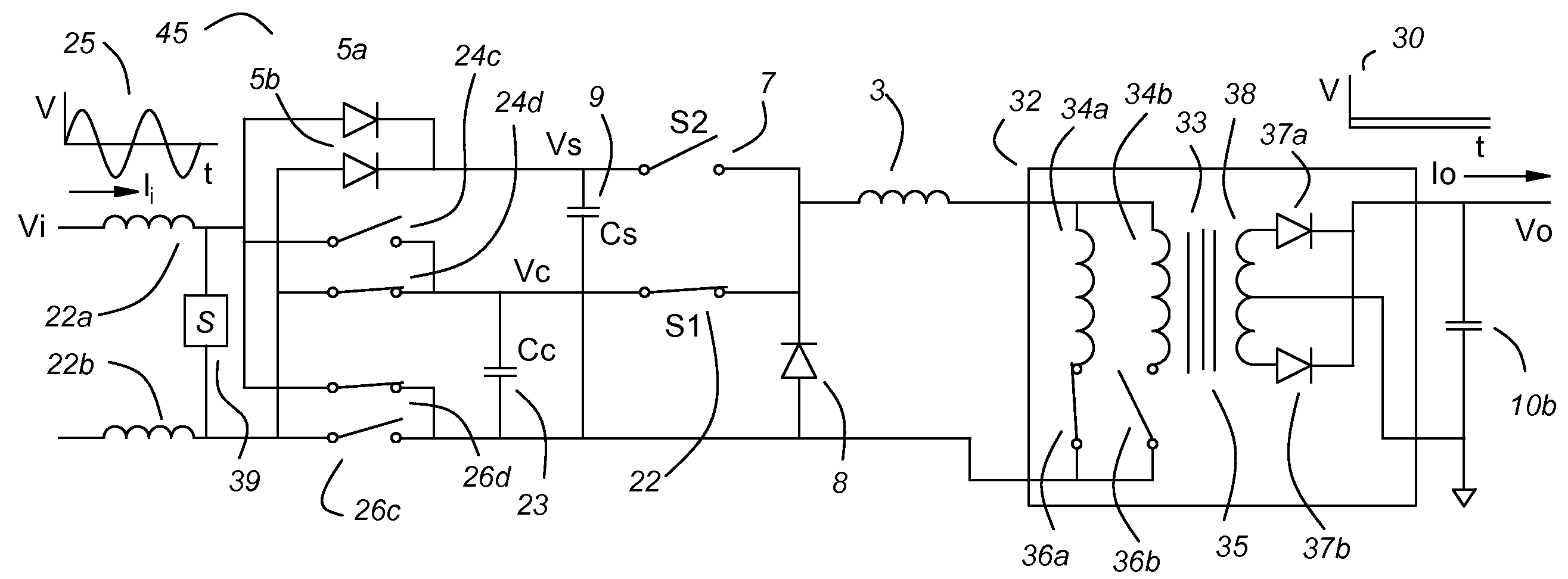
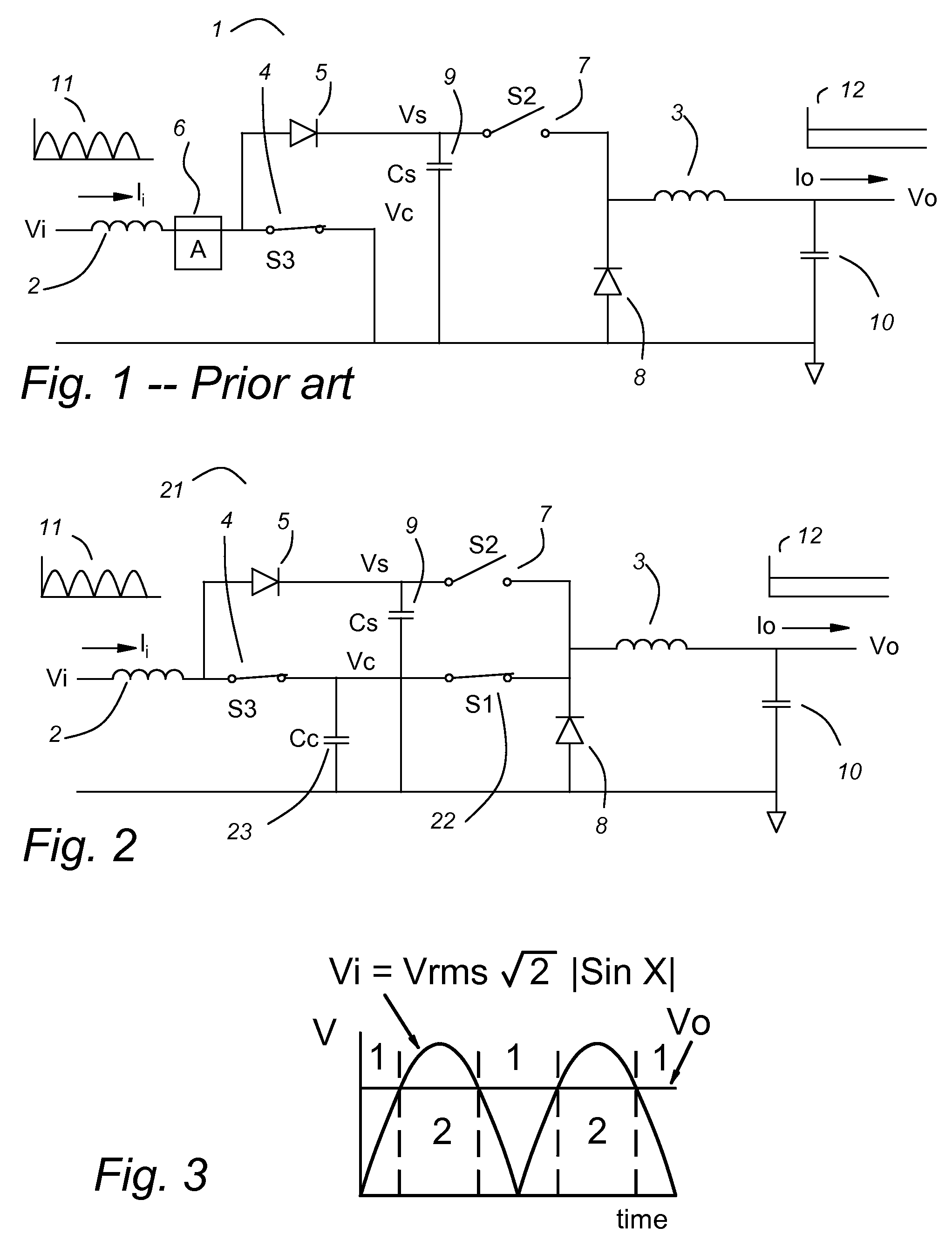
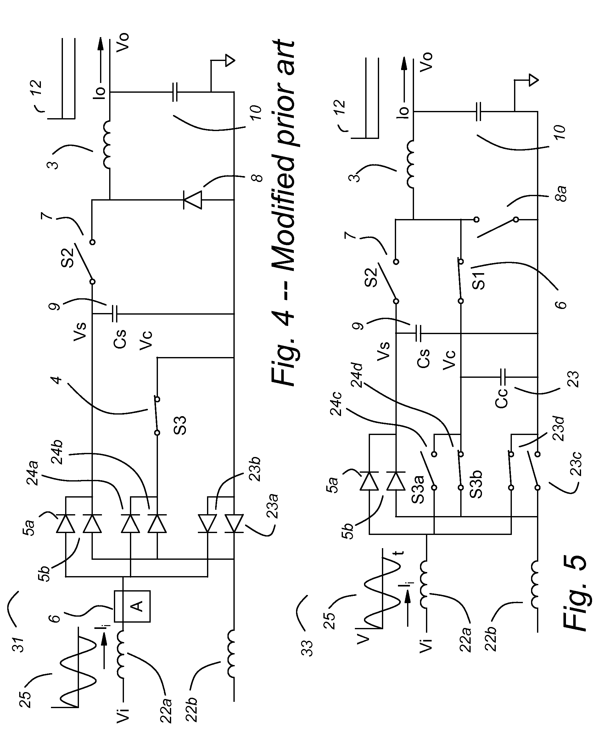
[0036]FIG. 1 shows a prior art power factor corrected (pfc) ac-dc converter 1. An input voltage Vi is a full wave rectified ac voltage, shown graphically by a graph 11. The input stage has a boost inductor 2 to smooth the input current Ii and to provide stored energy for the boost function. A switch 4 connects the boost inductor 2 to the return. When the switch 4 opens, current flows from the boost inductor 2 through a boost rectifier 5 to a storage capacitor 9. The output stage has a buck inductor 3 to smooth an output current and to provide stored energy for the buck function. When a switch 7 closes, current flows from the storage capacitor 9 to the buck inductor 3. When the switch 7 opens, the current flows through a catch rectifier 8. An output capacitor 10 further smoothes a dc output voltage Vo, shown graphically by a graph 12.

[0037]The prior art pfc ac-dc converter requires an input current measurement 6 to control the boost switch 4. The storage capacitor 9 typically is at a...


PUM


Abstract

A power factor corrected (pfc) ac-dc converter has a modified boost input and a modified buck output. Unlike the prior art boost input, the boost switch returns to the output, not to ground. Unlike the prior art buck output stage, a third switch connects to the input. This allows much of the input current to pass through the converter to the output. There is no input current measurement, but nearly ideal power factor correction is achieved through “natural modulation.” A preferred pfc ac-dc converter uses a variable dc-dc transformer on its output, as a post regulator, to provide dielectric isolation and to provide voltage level shifting. The output of the pfc ac-dc converter has the control characteristics of a buck converter, so it is a natural mate for the variable dc-dc transformer. An ac-dc buck converter is most efficient at its maximum duty cycle. It cannot regulate for a lower input voltage, but it can reduce its duty-cycle to control for higher input voltages. A variable dc-dc transformer is most efficient at its maximum ratio. It cannot regulate for a higher input voltage, but it can reduce its effective turns ratio to control for a lower input voltage. With a small overlap in their control ranges, both parts of the power system can operate at maximum efficiency. The variable dc-dc transformer controls the output voltage for nominal and low input voltage. The ac-dc buck converter limits over-voltage transients.

Description

CROSS REFERENCE TO RELATED APPLICATIONS[0001]This application is a continuation in part of the following patent application:Ser. No. 11 / 767,516, filed Jun. 24, 2007, and entitled “Natural Modulation for Maximizing Efficiency in Power Converters”[0002]This application claims priority to the following provisional patent applications:Ser. No. 60 / 805,715, filed Jun. 23, 2006, and entitled “Using “Natural Voltage” to Maximize Efficiency in Power Converters.”Ser. No. 60 / 807,056, filed Jul. 11, 2006, and entitled Power Factor Corrected Single-Phase AC-DC Power Converter Using Natural Modulation.”Ser. No. 60 / 807,499, filed Jul. 16, 2006, and entitled “Power Factor Corrected Single-Phase AC-DC Buck Power ConverterSer. No. 60 / 820,993, filed Aug. 1, 2006, and entitled “Natural Modulation”Ser. No. 60 / 866,613, filed Nov. 21, 2006, and entitled “Three-phase PFC Ac-Dc Converter having “100 Percent Duty Cycle,” andSer. No. 60 / 890,539, filed Feb. 19, 2007, and entitled “100% Duty-Cycle Buck-derived ...

Claims


Application Information

Patent Timeline
IPC IPC(8): H02M7/00G05F1/00H02M7/04H02M7/217H02M1/12H02M5/40
CPCG05F1/70H02M1/4258H02M1/4208Y02B70/126Y02B70/10Y02P80/10
Inventor HERBERT, EDWARD
Owner HERBERT EDWARD
Learn More