Systems and Methods for Modeling 3D Geological Structures

a geological structure and modeling system technology, applied in the field of three-dimensional (3d) geological structures, can solve the problems of not being suitable for integration into workflows for dynamic inversion and automated history matching of reservoir models, mps technology, and high difficulty in describing the above-mentioned structures

Active Publication Date: 2011-08-25
LANDMARK GRAPHICS
View PDF9 Cites 58 Cited by
  • Summary
  • Abstract
  • Description
  • Claims
  • Application Information

AI Technical Summary

Benefits of technology

[0008]The present invention meets the above needs and overcomes one or more deficiencies in the prior art by applying an integration method to calculate the shortest distance between two points of interest in a grid-less model of a geological structure and to determine which direction / orientation to use for correctly describing the local anisotropy effects.

Problems solved by technology

The two-point correlation is modeled through the definition of a variogram, which makes the description of the above-mentioned structures highly challenging if not impossible.
Although this technique is more efficient than traditional well-known algorithms, like Cholesky decomposition, it is not suitable for integration into workflows for dynamic inversion and automated history matching of reservoir models due, in part, to its dependence on the use of variogram definition.
MPS technology, however, still has its disadvantages such as, for example: a) dependence on the training image or training data set; and b) very long computational times for generating new geological model / realization.

Method used


Image

  • Systems and Methods for Modeling 3D Geological Structures
  • Systems and Methods for Modeling 3D Geological Structures
  • Systems and Methods for Modeling 3D Geological Structures

Examples


Embodiment Construction

[0022]The subject matter of the present invention is described with specificity, however, the description itself is not intended to limit the scope of the invention. The subject matter thus, might also be embodied in other ways, to include different steps or combinations of steps similar to the ones described herein, in conjunction with other technologies. Moreover, although the term “step” may be used herein to describe different elements of methods employed, the term should not be interpreted as implying any particular order among or between various steps herein disclosed unless otherwise expressly limited by the description to a particular order.

Method Description

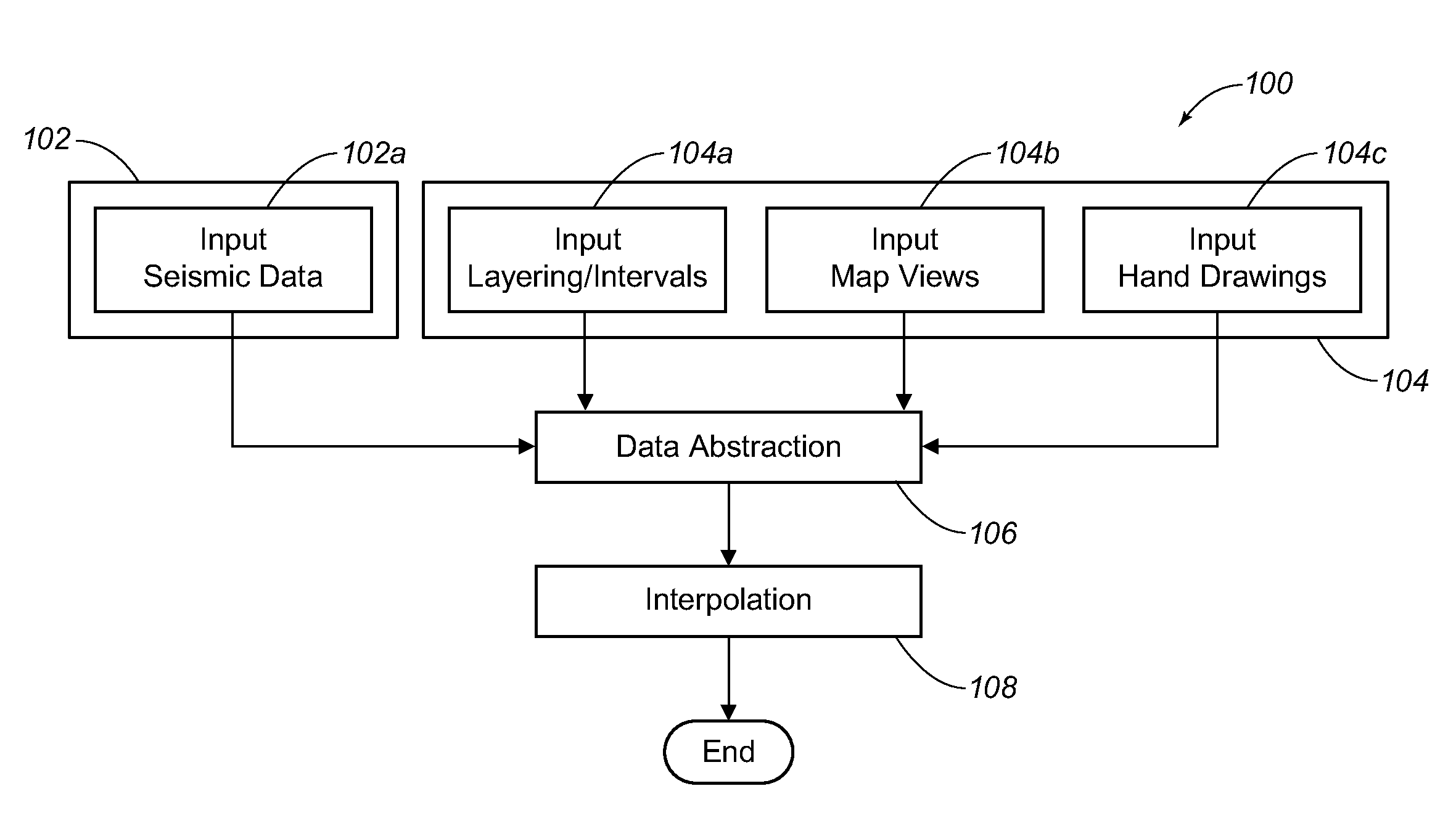
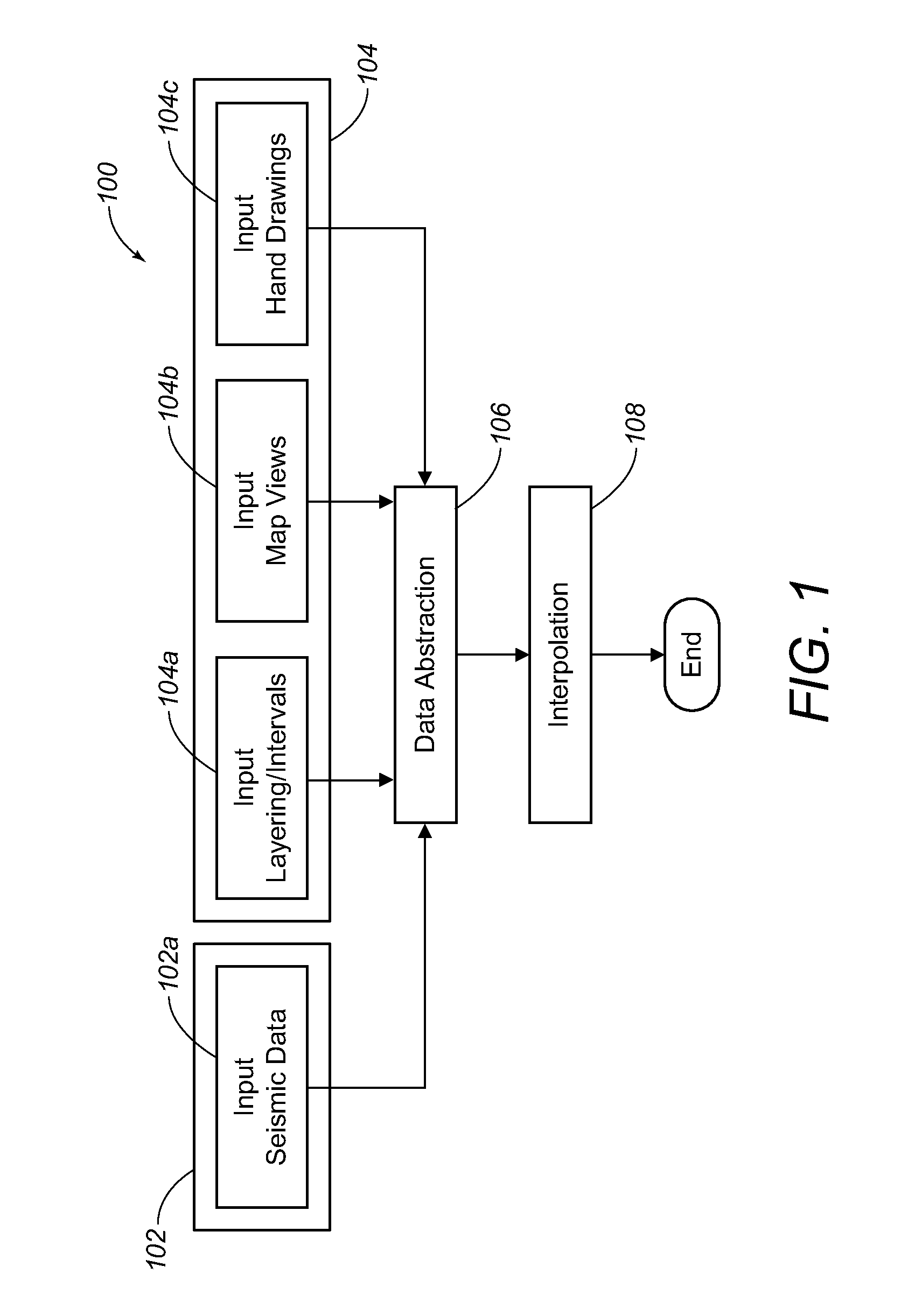
[0023]The following description includes one or more methods (hereinafter generally referred to as an “integration method”) for integrating the Point Vector technology and curvilinear point-to-point (CPP) interpolation techniques, which are well known in the art, through data abstraction to merge a broad range of availab...


PUM


Abstract

Systems and methods for modeling a three-dimensional (3D) geological structure to improve maximum continuity interpolation. An integration method describes local anisotropic effects and introduces interpolation techniques to perform the interpolation between two points of interest along a direction of maximum continuity and across fault surfaces.

Description

FIELD OF THE INVENTION[0001]The present invention generally relates to modeling three-dimensional (3D) geological structures. More particularly, the present invention relates to an integration method for maximum continuity interpolation in 3D geological modeling.BACKGROUND[0002]Conventionally, geostatistical software describes the pattern of spatial variation in geological properties (e.g. porosity and permeability) using a variogram model that quantifies the average of expected variability as a function of distance and direction. In reservoirs, where the geological characteristics are very continuous and easily correlated from well to well, the range (or scale), of correlation will be large and in reservoirs, where the geological characteristics change quickly over short distances, the range (or scale) of correlation will be smaller.[0003]In certain geological environments, the range of correlation may be directionally independent. This phenomenon is very common in sedimentary envi...

Claims


Application Information

Patent Timeline
Patent Type & Authority Applications(United States)
IPC IPC(8): G01V1/30G01V1/28
CPCG01V99/00G01V1/00G06T17/00G01V2210/665G01V2210/66G01V1/28
Inventor MAUCEC, MARKOYARUS, JEFFREY M.LIANG, LUMING
Owner LANDMARK GRAPHICS
Why Eureka
Try Eureka