Content reproduction system, content receiving apparatus, sound reproduction apparatus, content reproduction method and program

a content and content technology, applied in the field of content reproduction systems, can solve problems such as difficulty in and achieve the effect of improving the reproduction quality of particularly audio data

Inactive Publication Date: 2011-08-25
SONY CORP
View PDF7 Cites 26 Cited by
  • Summary
  • Abstract
  • Description
  • Claims
  • Application Information

AI Technical Summary

Benefits of technology

[0019]According to the embodiments of the present invention described above, reproduction quality of particularly audio data can be improved in reproduction of broadcast wave content.

Problems solved by technology

Therefore, there is an issue in reproduction of broadcast wave content that even if a clock generator capable of generating a very high-quality clock is mounted on an audio device, it is difficult to improve reproduction quality of particularly audio data.

Method used


Image

  • Content reproduction system, content receiving apparatus, sound reproduction apparatus, content reproduction method and program
  • Content reproduction system, content receiving apparatus, sound reproduction apparatus, content reproduction method and program
  • Content reproduction system, content receiving apparatus, sound reproduction apparatus, content reproduction method and program

Examples


first embodiment

[0049][Configuration example of the AV system]

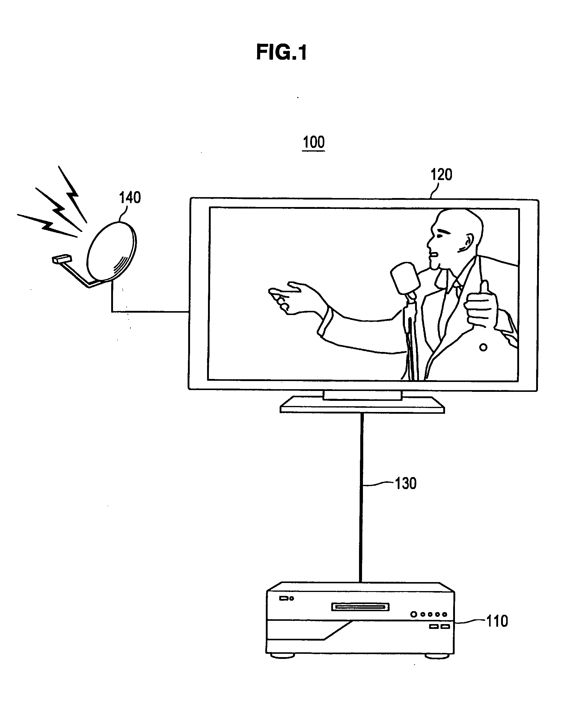
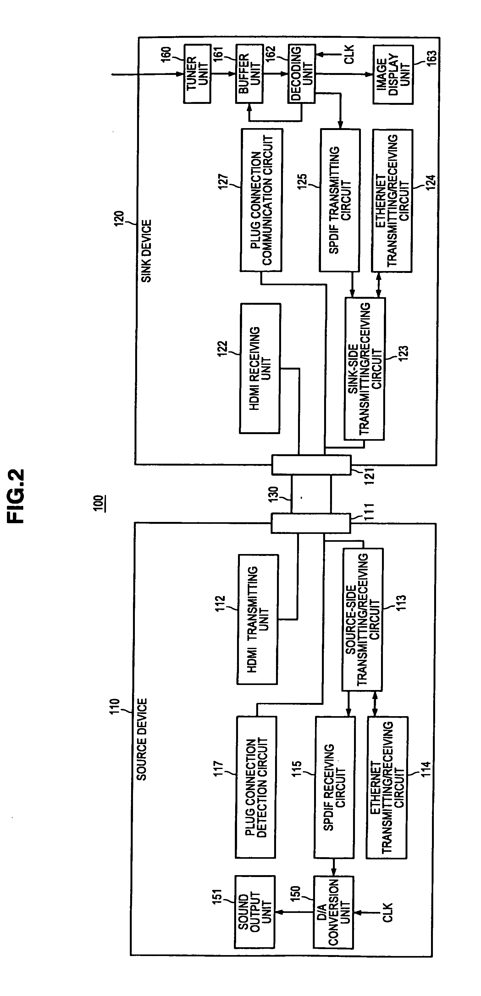
[0050]First, an AV system according to a first embodiment of the present invention will be described. FIG. 1 is a diagram schematically showing the configuration of an AV system according to the first embodiment of the present invention. FIG. 2 is a block diagram schematically showing the configuration of the AV system in FIG. 1.

[0051]In FIGS. 1 and 2, an AV system 100 is a system capable of reproducing broadcast wave content and includes a source device 110 such as an audio device and a sink device 120 such as a television apparatus. In the AV system 100, the source device 110 and the sink device 120 are HDMI HEAC (HDMI Ethernet and Audio Return Channel) compatible devices. An HDMI HEAC compatible device means having a communication unit that performs communication using a communication path with an HEAC+ line and HEAC− line constituting an HDMI cable.

[0052]The source device 110 and the sink device 120 are connected via an HDMI cable 13...

second embodiment

[Configuration Example of the AV System]

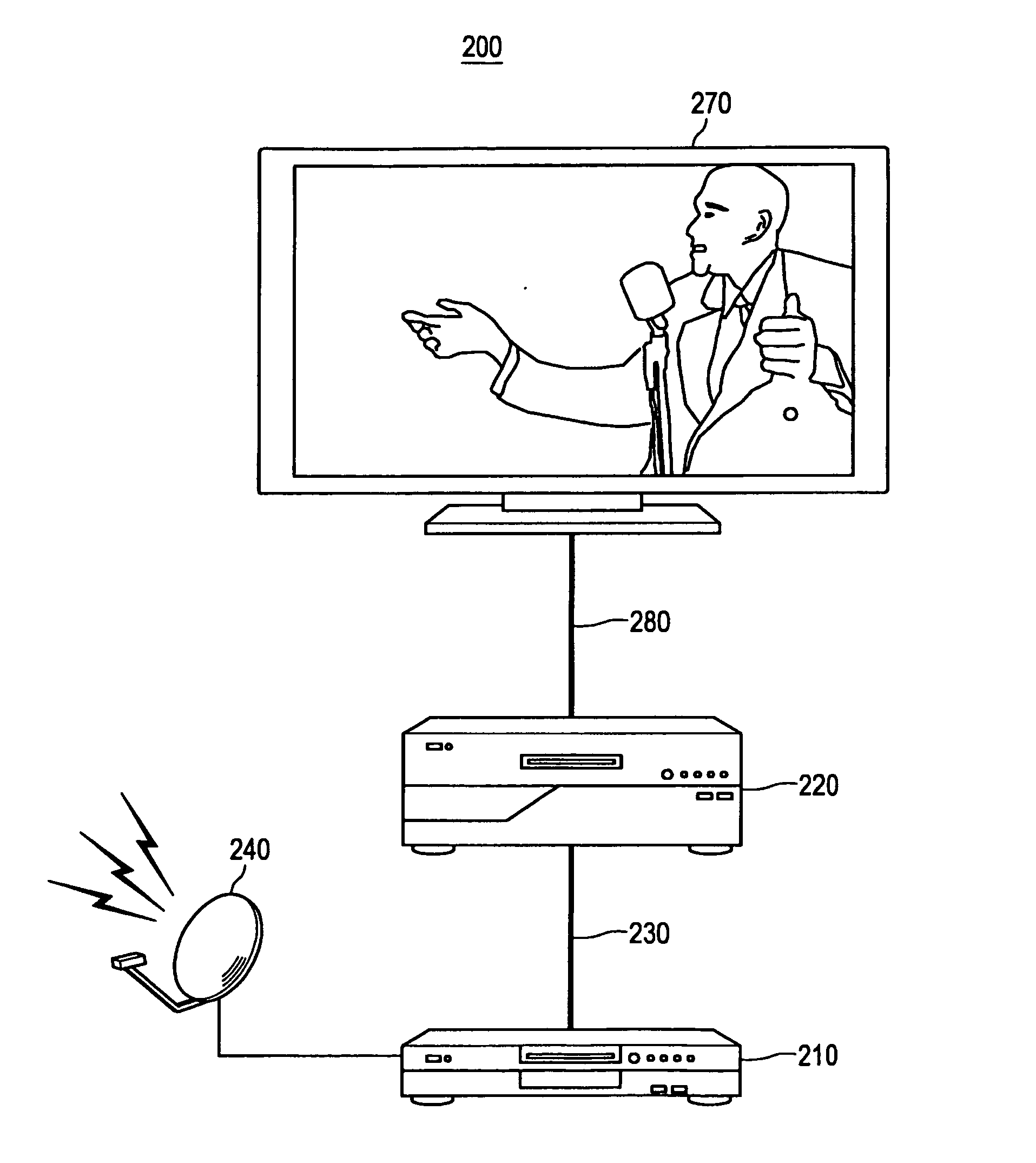
[0249]First, an AV system according to a second embodiment of the present invention will be described. FIG. 22 is a diagram schematically showing the configuration of an AV system according to the second embodiment of the present invention. FIG. 23 is a block diagram schematically showing the configuration of the AV system in FIG. 22.

[0250]In FIGS. 22 and 23, an AV system 200 is a system capable of reproducing broadcast wave content and includes a source device 210 such as a set-top box (STB), a repeater device 220 such as an audio device, and a sink device 270 such as a television apparatus. In the AV system 200, the source device 210, the repeater device 220, and the sink device 270 are HDMI HEAC compatible devices. An HDMI HEAC compatible device means having a communication unit that performs communication using a communication path with an HEAC+ line and HEAC− line constituting an HDMI cable.

[0251]The source device 210 and the repeater dev...


PUM


Abstract

There is provided an AV system including a sink device including a tuner unit that receives and demodulates broadcast wave content, a buffer unit that stores a stream as a demodulation result, a decoding unit that decodes the stored stream by reading the stream from the buffer unit, an SPDIF transmitting circuit that transmits audio data of a decoding result to a source device, and a sink-side transmitting/receiving circuit capable of transmitting/receiving a clock signal used by the decoding unit for decoding a stream to/from the source device and the source device including an SPDIF receiving circuit that receives the audio data transmitted by the SPDIF transmitting circuit and a source-side transmitting/receiving circuit capable of transmitting/receiving the clock signal used by the decoding unit for decoding the stream to/from the sink device.

Description

CROSS-REFERENCE TO RELATED APPLICATION[0001]The present application claims priority from Japanese Patent Application No. JP 2010-036148 filed in the Japanese Patent Office on Feb. 22, 2010, the entire content of which is incorporated herein by reference.BACKGROUND OF THE INVENTION[0002]1. Field of the Invention[0003]The present invention relates to a content reproduction system, a content receiving apparatus, a sound reproduction apparatus, a content reproduction method, and a program.[0004]2. Description of the Related Art[0005]In recent years, as AV (Audio / Video) devices handling a digital signal such as an audio signal and a video signal become increasingly available, various systems of interface to transmit the digital signal between these AV devices have been proposed. Among such interfaces, for example, the IEEE (Institute of Electrical and Electronics Engineers) 1394 standard and the HDMI (High-Definition Multimedia Interface) standard (HDMI is a registered trademark) are wid...

Claims


Application Information

Patent Timeline
Patent Type & Authority Applications(United States)
IPC IPC(8): H04N5/917G10L21/00
CPCG11B20/00086G09G2370/22G11B2020/10546H04N5/44H04N5/765H04N21/2368H04N21/2541H04N21/4307H04N21/4341H04N21/43632H04N21/4622H04N21/835G09G5/006G09G5/12G09G2370/045G09G2370/06G09G2370/12G11B2020/10537H04N21/43072
Inventor TOBA, KAZUAKIICHIMURA, GEN
Owner SONY CORP
Why Eureka
Try Eureka