Force multiplying retaining straps

a technology of retaining straps and force, which is applied in the direction of fastenings, press-button fasteners, transportation items, etc., can solve the problems of limiting the usefulness of restraints in cramped surroundings associated with articulated lifting assemblies, affecting the effect of restraining or releasing, and cluttered space occupied by the components of articulated lifting mechanisms, so as to achieve the effect of effective restraining or releasing and saving fabrication costs

Inactive Publication Date: 2011-09-01
MILLER ROBERT W
View PDF15 Cites 9 Cited by
  • Summary
  • Abstract
  • Description
  • Claims
  • Application Information

AI Technical Summary

Benefits of technology

[0016]Briefly, these and other objects are accomplished within the present invention by conforming a single piece frame of a cam buckle to include a plurality of transverse pivot rollers bridging across the lateral walls of the frame distal of the spring loaded pivoted lever carrying the cam that clamps the load carrying strap captured within the frame. A manually articulated eccentrically pivoted interlock is also mounted to bridge across the frame adjacent to the free end of the release lever to select its releasing displacement by the gap in the eccentric projection thereof but to oppose the release of the strap throughout all the its other radial alignments, thus accommodating a single-handed restraining sequence of the carried vehicle. The selective placement of the foregoing pivot rollers relative the cam lever pivot are then useful to multiply the number of loops of the load carrying strap and also to selectively support a pivoted tongue panel extending between the strap layers compressed by the cam to increase the cam forces that capture the free end of the strap.
[0017]Alternatively, the pivot axis and radial dimensions of the turning roller which aligns the strap onto the tongue, and also the arcuate form of the tongue, may each be selected so the stretched strap portion extending thereover contacts the underside of the release lever so that the increasing strap tension effects an interlock. In this form the interlock itself may be omitted as the mechanism is thus rendered self effecting. Of course, this last form obtains even further simplifying results as the strap induced forces opposing the release lever effectively also replace the function of the springs.
[0019]It will be appreciated that in the normal course only one cam buckle assembly is needed to effectively perform any restraining or release. The complementing second piece that forms the other part of the pulley assembly may therefore be implemented as a single frame piece only, omitting the latching lever to conserve fabrication costs thereby utilizing a single fabrication process for both ends of the pulley assembly thus obtained.

Problems solved by technology

These restraints often require very large tension levels, particularly when robust suspension elements need to be controlled.
Thus while suitable for the purposes intended, the need for a wind-up mechanism and a lever dimension necessary to produce the desired level of force limits the usefulness thereof in the cramped surroundings associated with an articulated lifting assembly.
Simply, the space that is cluttered by the components of an articulated lifting mechanism leaves little accommodation for any fixed wind-up mechanisms, operated by levers and the like, particularly when variously shaped carried vehicles are entailed.

Method used


Image

  • Force multiplying retaining straps
  • Force multiplying retaining straps
  • Force multiplying retaining straps

Examples


Embodiment Construction

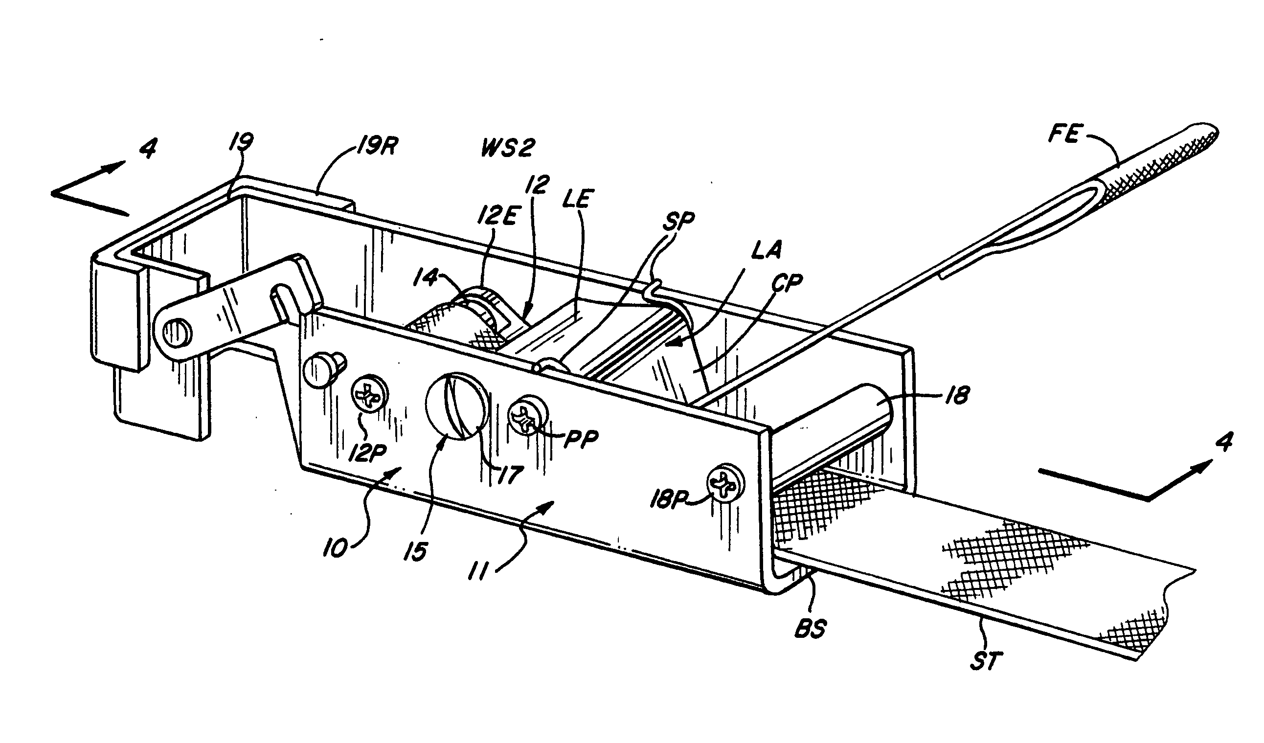
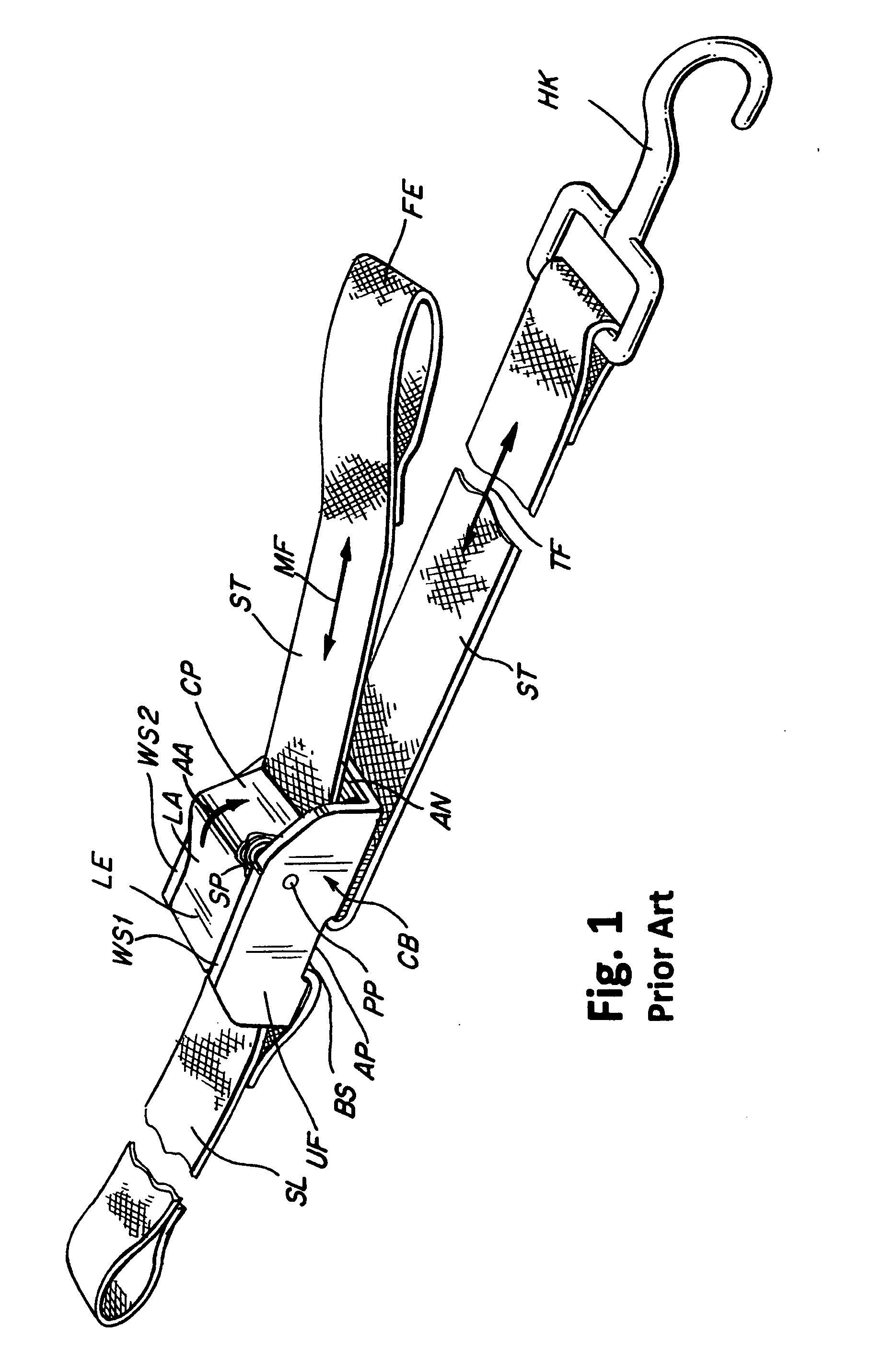
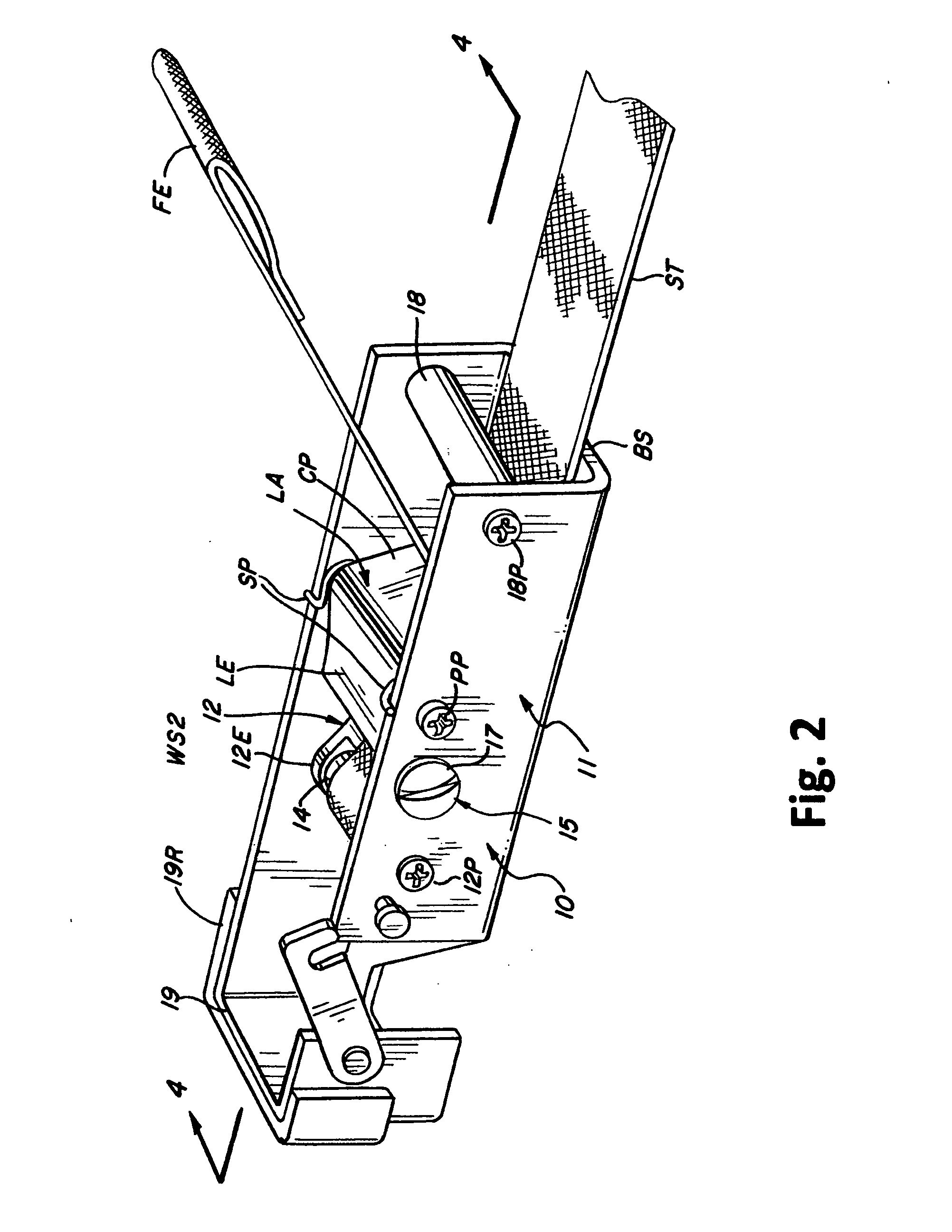
[0028]As shown in FIG. 1 a conventional cam buckle assembly generally designated CB comprises a single piece unitary frame UF of a generally C-shaped section defined by a bottom surface BS spanning between two lateral walls WS1 and WS2. A transverse pivot pin PP extends between the walls WS1 and WS2 proximate the one ends thereof to support an L-shaped lever assembly LA at the junction of a lever LE and a generally orthogonal cam piece CP.

[0029]A helical bias spring SP on pin PP is compressed between wall WS1 and the lever LE to urge the free end of the cam piece CP in the direction of arrow AA towards an anvil piece AN supported on the bottom surface BS, capturing a load carrying strap ST therebetween as it is passed through an aperture AP in the bottom surface BS against the tension force TF carried by the strap to an end hook HK corresponding to the manually applied tensioning force at the strap's free end FE. A strap loop SL around the other portion of the bottom surface BS bord...


PUM


Abstract

A generally U-sectioned cam buckle frame is modified to include a first turning roller aligned transversely across the frame proximate the free end of a release lever. A generally planar tongue having one end pivoted adjacent the first roller extends within the frame under the cam piece connected to the release lever provides a force transfer structure for a strap is inserted between the tongue and the frame bottom surface, around the first roller to pass between the cam piece and the other side of the tongue. Other transverse rollers may be included in the frame to form a pulley arrangement and one end of a frame side wall may be convolved to form a hook assembly.

Description

REFERENCE TO RELATED APPLICATIONS[0001]This application is a continuation-in-part of U.S. patent application Ser. No. 12 / 802,845 filed on Jun. 15, 2010 which, in turn, obtains the benefit of the earlier filing date of US Provisional Application Ser. No. 61 / 338,993 filed on Mar. 1, 2010 and the benefit of this earlier filing date is claimed for all matter common therewith.BACKGROUND OF THE INVENTION[0002]1. Field of the Invention[0003]The present invention relates to motorcycle transport restraints, and more particularly to restraining strap clasping mechanisms combined with pulley pivots for increasing the force levels obtained from the combination.[0004]2. Description of the Prior Art[0005]The outdoor recreation customs and habits that have developed here in the United States adapted to the grandiose and large landscapes of the country, with a consequent reliance on all sorts of motorized vehicles that either bring us closer to nature, as for example the motorcycle, or are speciali...

Claims


Application Information

Patent Timeline
Patent Type & Authority Applications(United States)
IPC IPC(8): A44B11/02
CPCY10T24/2175B60P7/083
Inventor MILLER, ROBERT W.
Owner MILLER ROBERT W
Why Eureka
Try Eureka