LED multi-chip bonding die and light strip using the same

Inactive Publication Date: 2011-09-01
PAN DINGGUO
View PDF12 Cites 13 Cited by
  • Summary
  • Abstract
  • Description
  • Claims
  • Application Information

AI Technical Summary

Benefits of technology

[0023]In one embodiment of the Light strip as mentioned above, the circuit board is a compound board or PCB with bakelite plate as the stratum and both sides thereof are

Problems solved by technology

From these experiments and the current status of products produced or sold, people find that the major technical b

Method used


Image

  • LED multi-chip bonding die and light strip using the same
  • LED multi-chip bonding die and light strip using the same
  • LED multi-chip bonding die and light strip using the same

Examples


Embodiment Construction

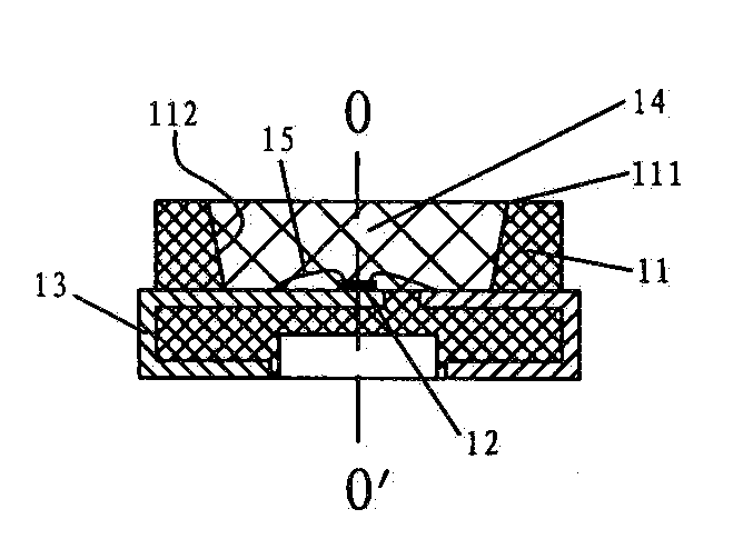
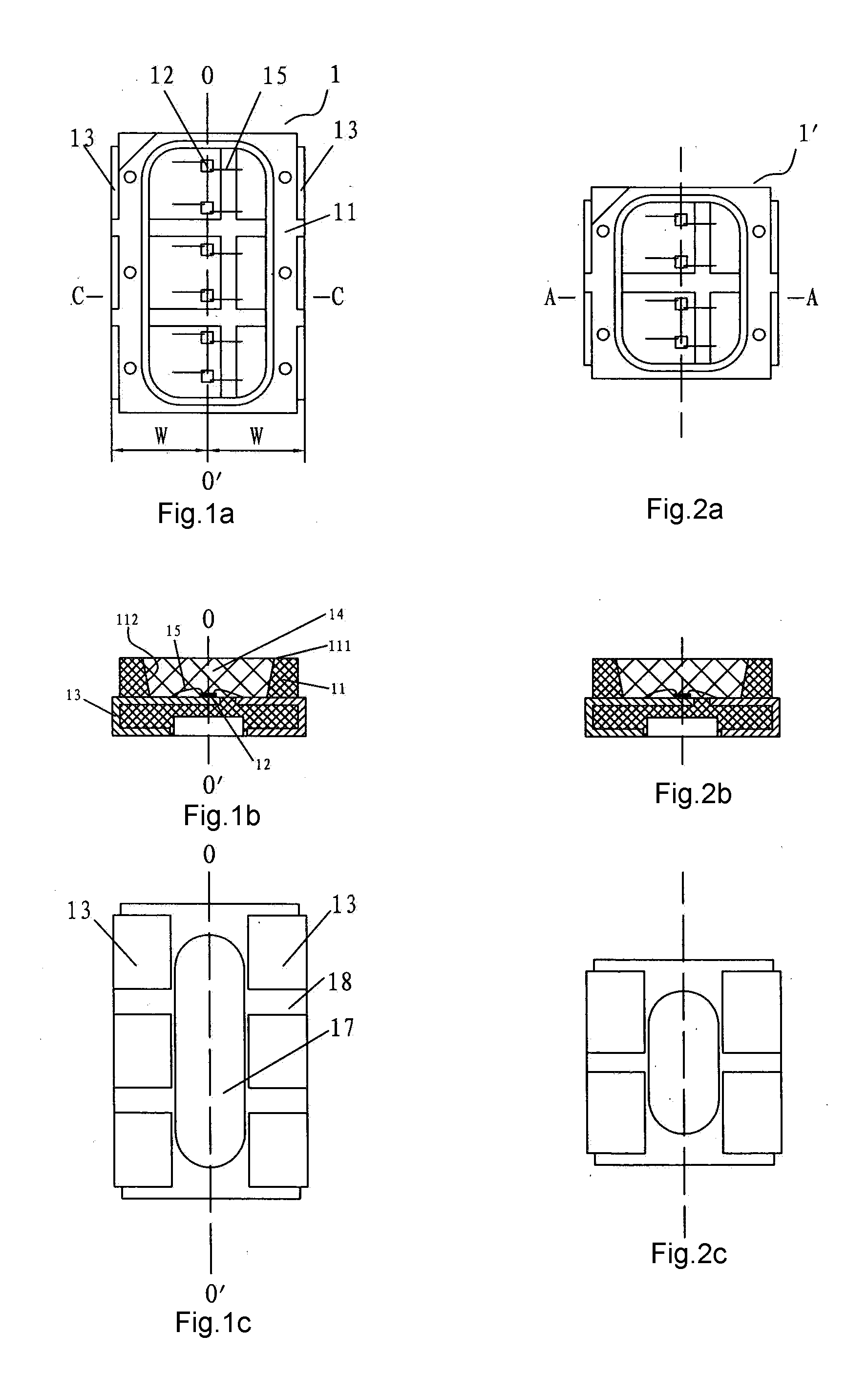
[0042]Refer to FIG. 1a to FIG. 2c, wherein the 3 views for the two structural distributions of the packaged LED multi-chip bonding die of the present invention are displayed. FIG. 1a to FIG. 1c show the distributed architecture of the bonding die equipped with six LED chips and FIG. 2a to FIG. 2c show the distributed architecture of the bonding die equipped with four LED chips. Whether they are 6 chips or 4 chips, the difference lies only in that different numbers of chips in multi-chip bonding die result in different numbers of electrodes and different light energy, but their architectures are essentially the same, except for their volume. Therefore, the embodiment of the invention is illustrated using the bonding die with six LED chips as an example.

[0043]The LED multi-chip bonding die 1 of the present invention comprises six LED chips 12, an electrode 13 and a packaging cover 14, wherein the upper surface 111 of the packaging enclosure 11 is equipped with a groove 112, the bottom...


PUM


Abstract

An LED multi-chip bonding die (1) comprises a packaging enclosure, a plurality of LED chips and a packaging cover, wherein the chips are arranged in one line from top to bottom on the emitting platform. Large area electrodes are equipped on the packaging enclosure and the packaging cover is made of transparent silicon gel so that the bonding die can emit larger light energy and higher luminance via the packaging cover while the heat produced by the chips can be quickly dissipated by the electrodes. A light strip (20) equipped with the bonding die comprises a plurality of bonding die sections and circuit board (2) and each bonding die section (1) comprises four LED multi-chip bonding dies (1) and a current-limiting resistor in series circuit. Each series circuit is connected in parallel and circuit board (2) is printed circuit board which can provide a optimal heat-dissipating structure for chips of bonding die.

Description

TECHNICAL FIELD[0001]This invention relates to a light emitting diode (LED) and more particularly to an LED multi-chip bonding die useful for light-reflecting plate with triangular prisms and to a light strip using the same. The bonding die is packaged with a plurality of LED chips.TECHNICAL BACKGROUND[0002]Under the pressure from demands which exceed supplies and increasing price of energy resources, the lighting industry hopes to seek for some lighting fixtures ideal both for lighting and energy conservation. Therefore, LED lighting fixtures appear and begin to substitute incandescent lamps and compact fluorescent lamps. To ensure extensive application and popularization of LED lighting fixtures, many scientific and technical staffs in this field and relevant fields have researched and developed high power LED light sources and published massive research articles and laboratory reports. From these experiments and the current status of products produced or sold, people find that th...

Claims


Application Information

Patent Timeline
IPC IPC(8): H01L27/15
CPCF21Y2101/02F21Y2105/001H01L25/0753H01L24/97H01L2224/48091H01L2924/12041H01L2224/45144H01L2924/00H01L2924/181F21Y2105/10F21Y2115/10H01L2924/00012H01L2924/00014H01L33/48H01L33/62
Inventor PAN, DINGGUO
Owner PAN DINGGUO
Why Eureka
Try Eureka