
Cable Arrangement Structure and Image Scanner Employing the Same

a technology of image scanner and cable arrangement, applied in the direction of cable arrangement between relatively moving parts, electric cable installation, thin material processing, etc., can solve the problems of reducing the yield rate and causing rapid damage to the cabl

Active Publication Date: 2011-09-01
BROTHER KOGYO KK
View PDF23 Cites 12 Cited by
  • Summary
  • Abstract
  • Description
  • Claims
  • Application Information

AI Technical Summary

Benefits of technology

[0009]According to aspects of the invention, the buckling of the cable is suppressed because of a configuration different from the conventional art so that monitoring of the Young's modulus is not necessitated.

Problems solved by technology

In such a case, the cable may be damaged quickly.
In the conventional art as described above, however, it is necessary to monitor the combined Young's modulus strictly since the bucking may occur if the Young's modulus decreases, which causes yield rate to be lowered.

Method used


Image

  • Cable Arrangement Structure and Image Scanner Employing the Same
  • Cable Arrangement Structure and Image Scanner Employing the Same
  • Cable Arrangement Structure and Image Scanner Employing the Same

Examples


first embodiment

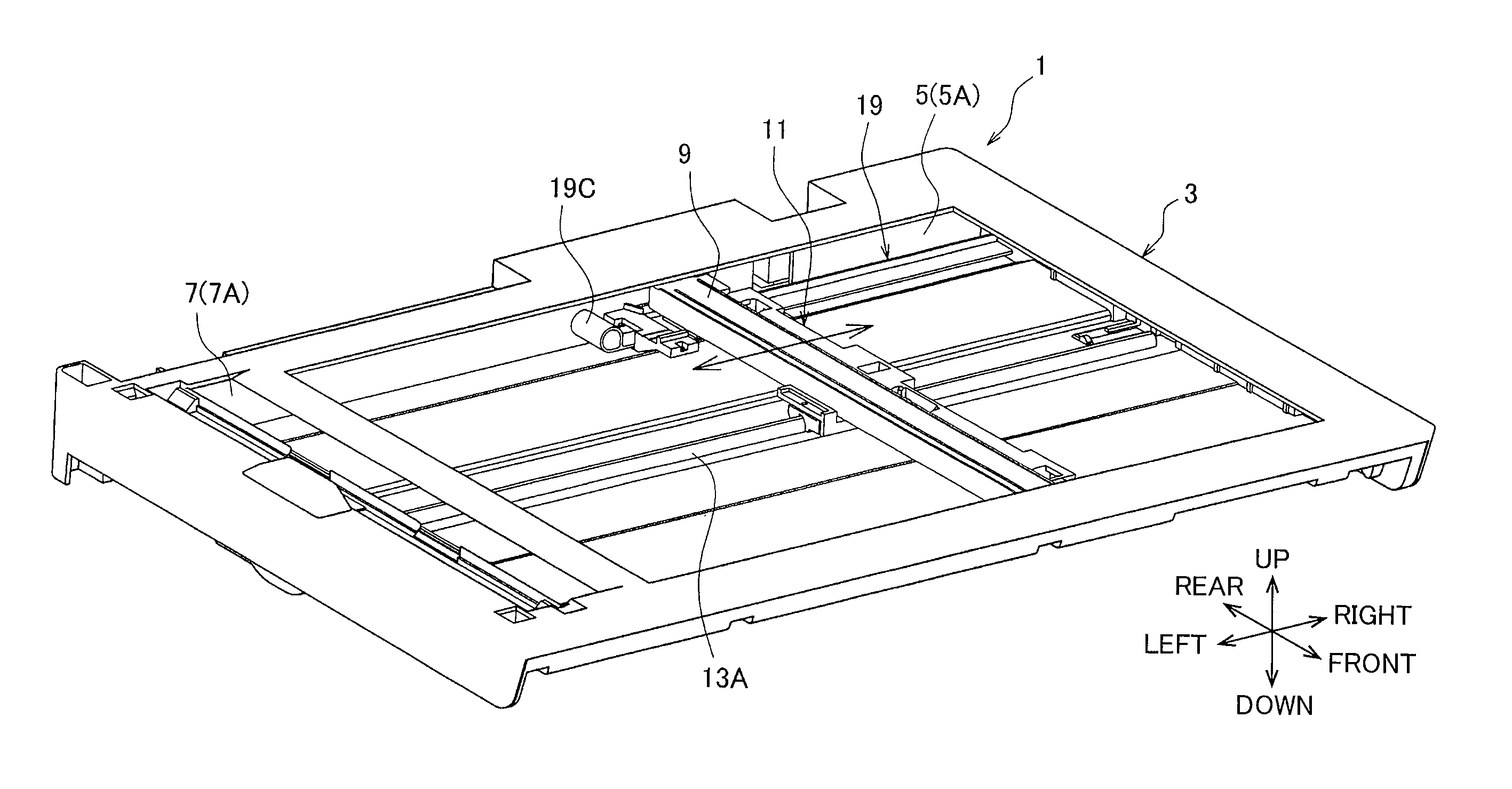
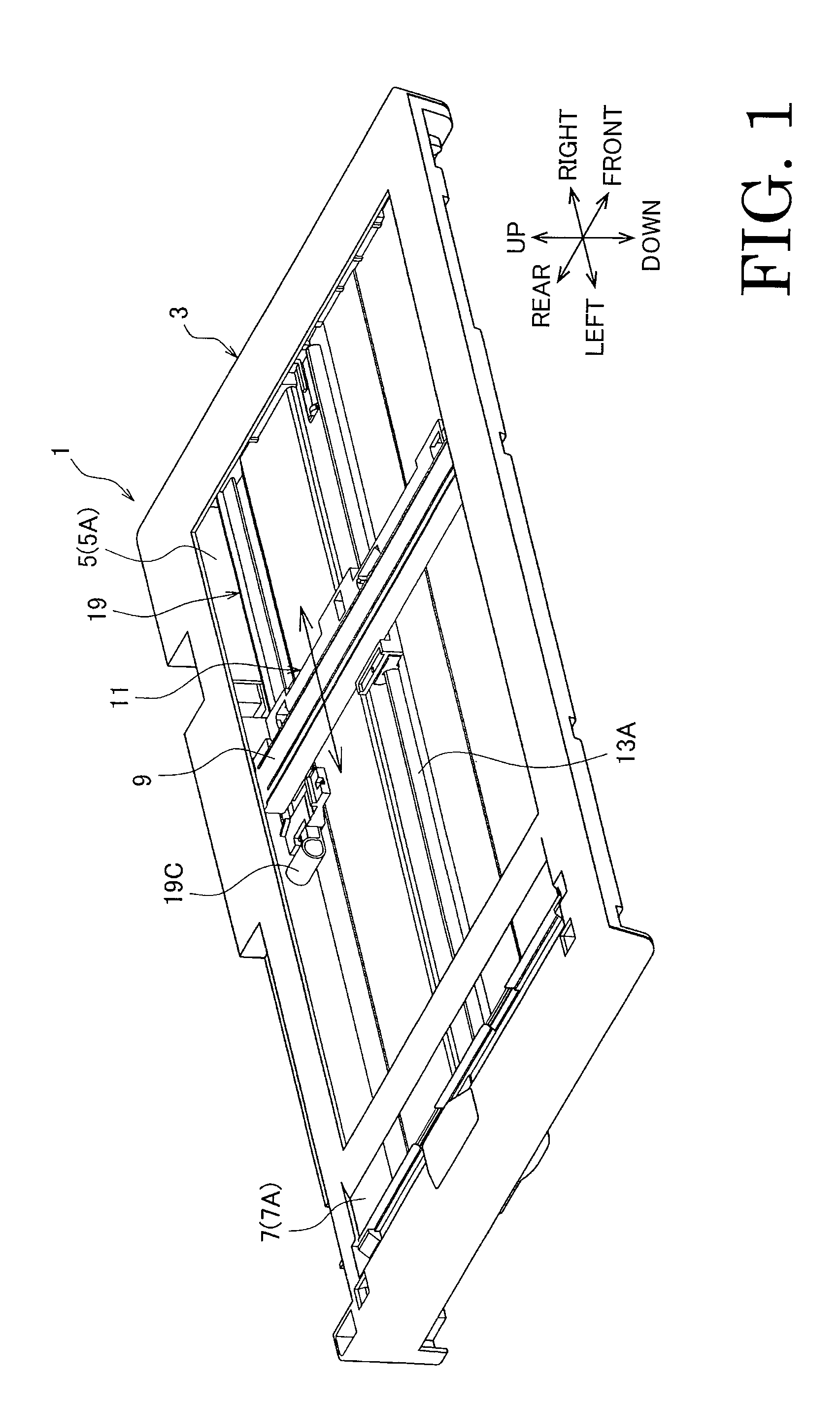
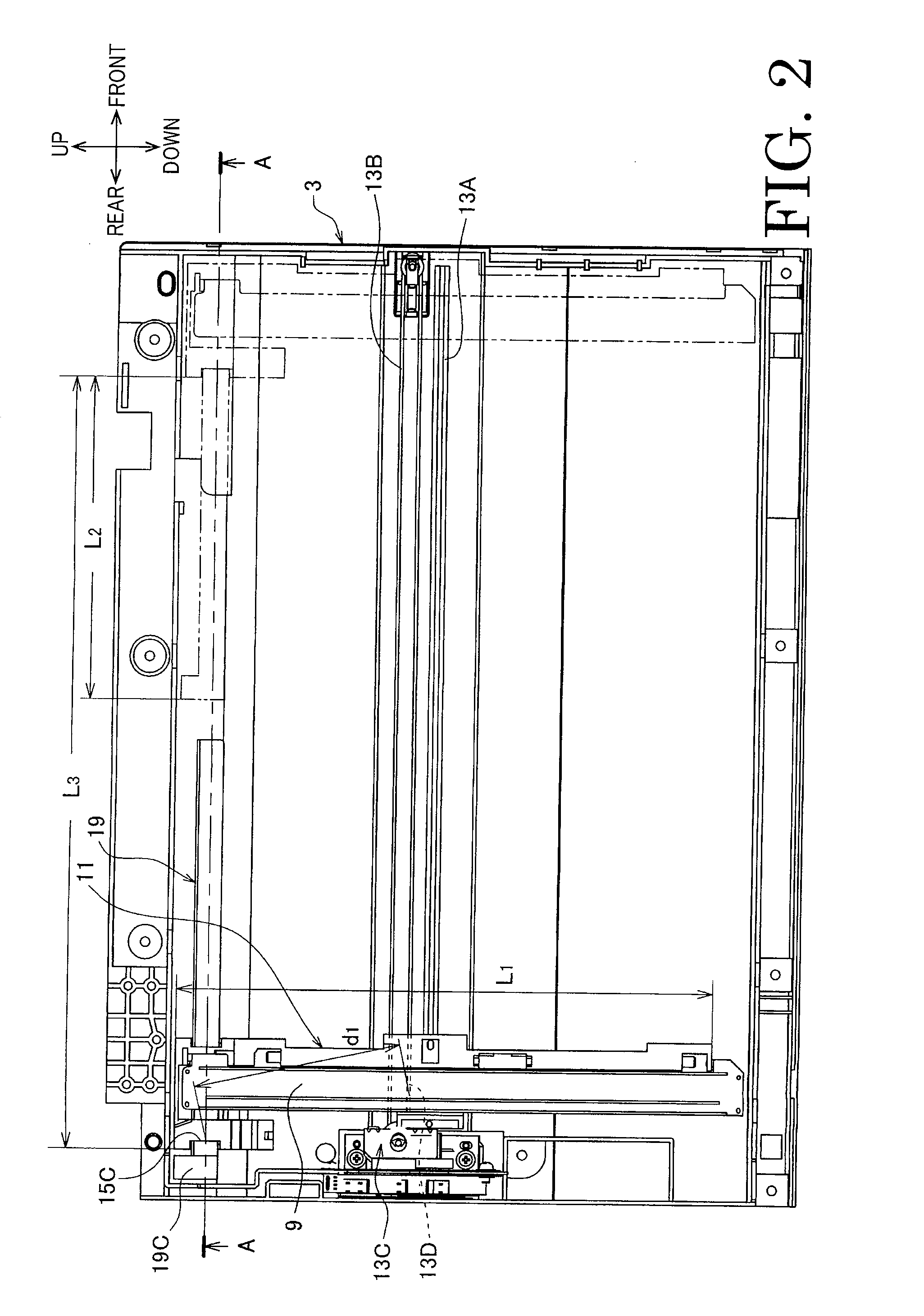
[0035] to prevent the straight portion 15B from buckling due to the compression force, a tension applying mechanism 17 is provided. The tension applying mechanism 17 contacts the curved portion 15A from an inner side of the curvature to apply tension to the cable 15.

[0036]As will be described, the tension applying mechanism 17 is configured to operate in mechanical association with the movement of the carriage 11 to apply tension to the cable 15 without using an electrical actuator.

[0037]As shown in FIG. 7, the tension applying mechanism 17 includes a tension bar 19 which is movably coupled to the carriage 11. The tension bar 19 is movable with respect to the carriage 11 in a carriage moving direction (i.e., right and left direction). The tension applying mechanism 17 further includes a resisting member 21 (see FIG. 8) which applies a resisting force to resist a displacement of the tension bar 19 to reduce a relative distance between the curved portion 15A and the carriage 11.

[0038]...

second embodiment

[0072]In the above-described, the plate spring is used as the resisting member 21. described below, another type of elastic member such as sponge or rubber is used as the resisting member 21 as shown in FIG. 10.

[0073]In the above-described embodiments, the resisting member 21 directly contacts the tension bar 19. The invention needs not be limited to such a configuration, and the resisting member 21 may indirectly contact the tension bar 19, with a certain member between the resisting member 21 and the tension bar 19. It is also possible that the tension bar 19 may indirectly contact the carriage 11.

[0074]According to the above-described embodiments, when the distance between the curved portion 15A and the carriage 11 reduces, tension is not always applied to the straight portion 15B. If the tension is applied to the cable 15 at certain timings when the carriage 11 is moved to approach the curved portion 15A, the buckling of the straight portion 15B can be suppressed necessarily an...


PUM


Abstract

A cable arrangement structure is provided with a movable body configured to reciprocally move relative to a base member, and a flexible cable transmitting electrical signals. One end of the flexible cable is fixedly connected to the base member, and another end is connected to the movable body. The flexible cable has a curved portion, and both ends of the flexible cable being located on a same side with respect to the curved portion. A tension applying unit configured to contact the curved portion of the flexible cable from an inner side of a curvature of the curved portion to apply tension to the flexible cable when the curved portion is located on a front direction of the movable body as moved. Application of the tension to the flexible cable is controlled in mechanical association with movement of the movable body.

Description

CROSS-REFERENCE TO RELATED APPLICATION[0001]This application claims priority under 35 U.S.C. §119 from Japanese Patent Application No. 2010-044270 filed on Mar. 1, 2010. The entire subject matter of the application is incorporated herein by reference.BACKGROUND[0002]1. Technical Field[0003]Aspects of the present invention relate to a cable arrangement structure and an image scanner employing the cable arranging structure.[0004]2. Related Art[0005]Conventionally, there has been known a cable arrangement structure employed, for example, in an image scanner. Specifically, such a cable arrangement structure is configured such that an end of a cable having a curved portion (e.g., U-shaped or J-shaped portion) is connected to a movable body (e.g., a scanning head) which reciprocates inside the image scanner.SUMMARY[0006]In the cable arrangement structure as described above, if the curved portion is located on a downstream side in a moving direction of the movable body, stress (a compressi...

Claims


Application Information

Patent Timeline
Patent Type & Authority Applications(United States)
IPC IPC(8): H04N1/04H02G11/00
CPCH04N1/00559H04N1/0083H04N1/103H04N1/1026H04N1/1017
Inventor KOZAKI, DAISUKEMAEKAWA, MIKI
Owner BROTHER KOGYO KK
Learn More