Vehicle rear portion structure

a rear portion and rear portion technology, applied in the direction of roofs, transportation and packaging, vehicle arrangements, etc., can solve the problem of not being able to directly support the load input from the rear suspension through the toroidal skeleton frame, and achieve the effect of reducing the weight of the respective internal reinforcing components and improving the ease of mounting

Inactive Publication Date: 2010-07-20
HONDA MOTOR CO LTD
View PDF5 Cites 2 Cited by
  • Summary
  • Abstract
  • Description
  • Claims
  • Application Information

AI Technical Summary

Benefits of technology

[0011]According to the above described vehicle rear portion structure, a horizontal cross section of the vehicle rear portion is reinforced by the toroidal skeleton frame that is formed with the parcel frame, the respective reinforcing frames, and the rear cross member. Furthermore, the load that is input from the rear suspension is directly supported by the toroidal skeleton frame that has high rigidity in response to torsion in the vehicle body. Namely, the load that is input on a plurality of mounting points for the rear suspension can be directly supported within a plane that is orthogonal to the vehicle longitudinal direction by means of the toroidal skeleton frame. Because of this, it is possible to efficiently improve the support rigidity of the rear suspension without causing any large increase in weight.
[0013]In this case, joint portions between both the edges of the parcel frame and the respective reinforcing frames are reinforced by the reinforcing components on the upper side of the rear wheel houses. Namely, on the upper side of the rear wheel houses, the joint portions between the parcel frame and the respective reinforcing frames can be reinforced by the reinforcing component having a closed section structure. As a result, it is possible to improve the rigidity of the joint portions between the parcel frame and the respective reinforcing frames while suppressing any buckling into the passenger compartment.
[0015]In this case, the bottom portions of the respective reinforcing frames, the respective rear frames, and the rear cross member are connected rigidly in a structure having a continuous cross section by means of the internal reinforcing components. Namely, as a result of the bottom end of each reinforcing frame being joined to the interiors of the respective concave portions of the rear frames, and as a result of the bottom end of each reinforcing frame, the concave portion in each rear frame, and the respective concave portions in the adjacent rear cross member being joined by means of the internal reinforcing components whose vertical cross sections which are parallel with the respective rear frames have substantially the same shape as the horizontal cross sections of the reinforcing frames, the bottom portions of the respective reinforcing frames, the respective rear frames, and the rear cross member form a structure which has a continuous cross section. As a result, it is possible to rigidly connect the three elements of the reinforcing frames, the rear frames, and the rear cross member while suppressing any buckling into the passenger compartment.
[0017]In this case, the bottom portions of the respective reinforcing frames, the rear frames, and the rear cross member are connected by means of a structure which has a continuous cross section that is formed with the first internal reinforcing component, the second internal reinforcing component, and the respective reinforcing frames. As a result, it is possible to rigidly connect the three elements of the reinforcing frames, the rear frames, and the rear cross member while suppressing any buckling into the passenger compartment.
[0020]In these cases, it is possible to achieve a reduction in the weight of the respective internal reinforcing components and an improvement in ease of mounting, while rigidly connecting the bottom portions of the respective reinforcing frames, the rear frames, and the rear cross member by means of a structure which has a continuous cross section that is formed with the first internal reinforcing component, the second internal reinforcing component, and the respective reinforcing frames.

Problems solved by technology

Because of this, it is impossible to directly support the load input from the rear suspension by means of the toroidal skeleton frame.

Method used


Image

  • Vehicle rear portion structure
  • Vehicle rear portion structure
  • Vehicle rear portion structure

Examples


Embodiment Construction

[0028]An embodiment of the present invention is described below based on the drawings. Note that in the description given below, unless specifically stated otherwise, ‘up’, ‘down’, ‘left’, and ‘right’ refer to the up, down, left, and right with respect to a vehicle 1 facing in a forward direction, respectively. In addition, the arrow F in the drawings points towards the front of the vehicle, while the arrow U points towards the top of the vehicle.

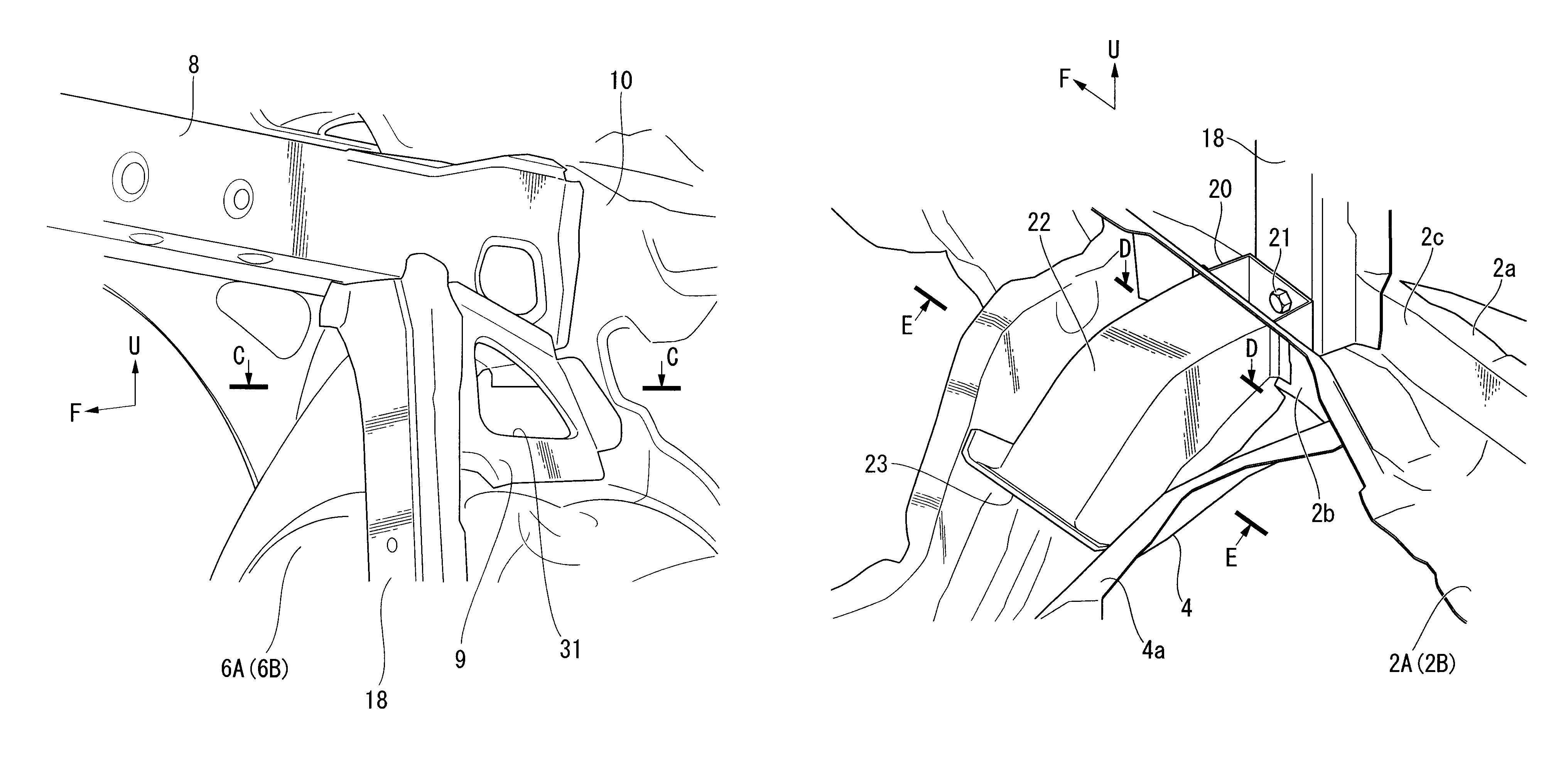
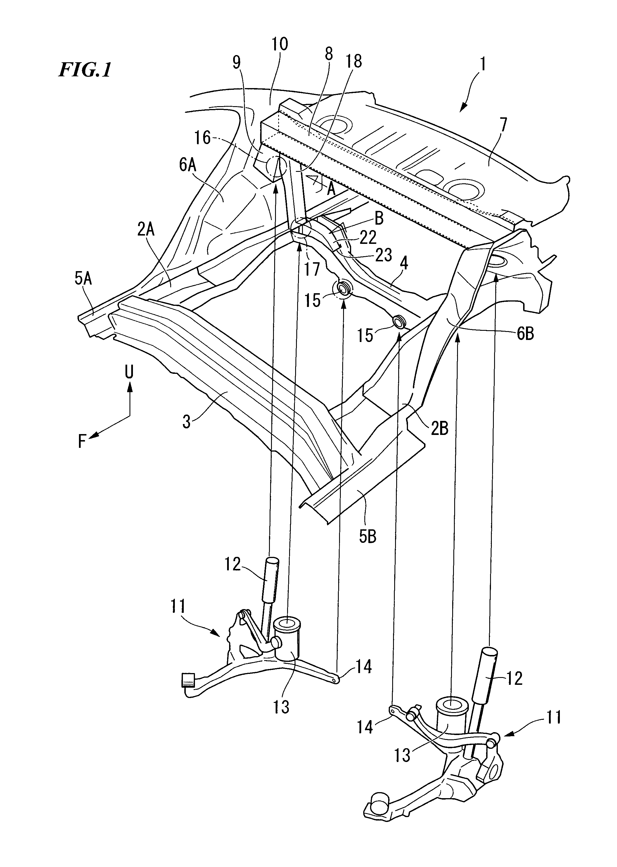
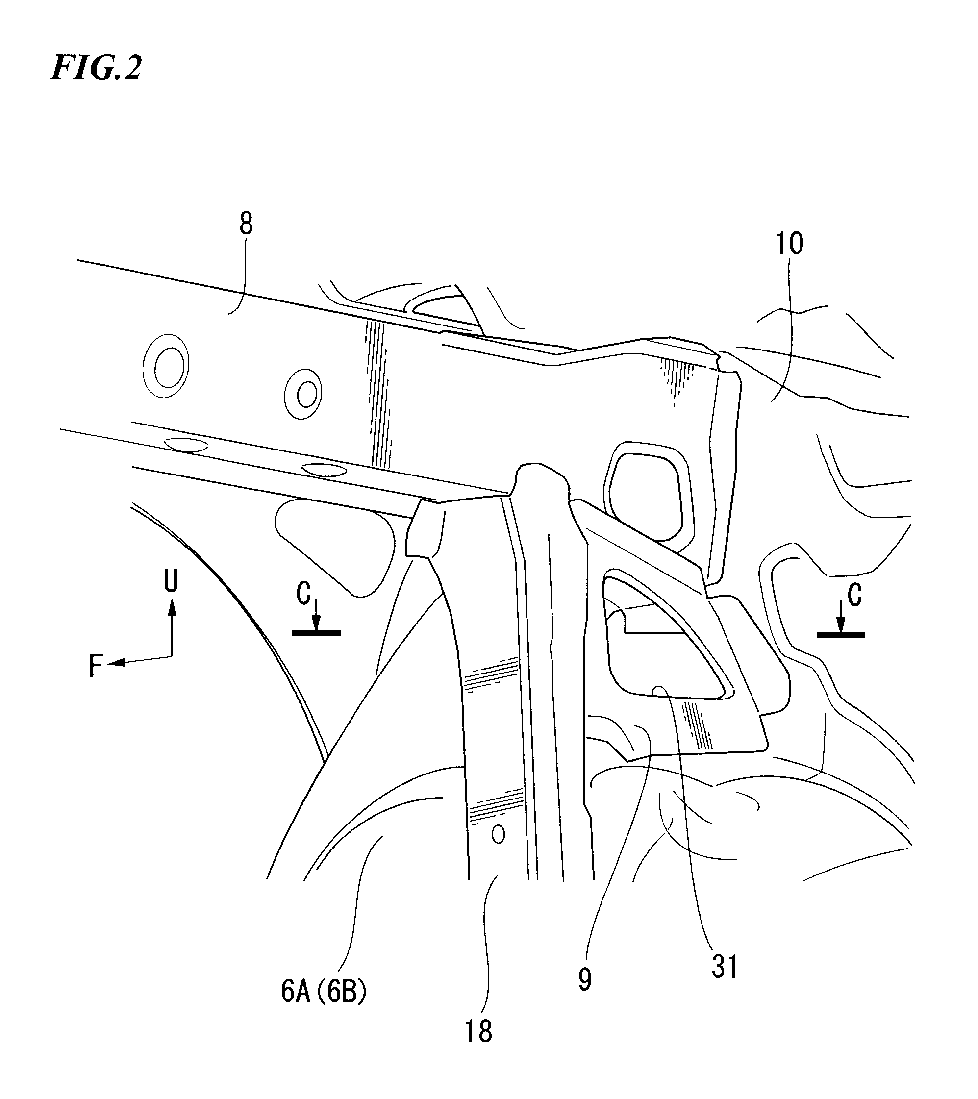
[0029]FIG. 1 shows a sedan vehicle 1 which employs the vehicle rear portion structure according to the embodiment of the present invention, and shows a rear portion of the longitudinally sliced vehicle 1 as seen from a diagonally forward and upward direction. FIGS. 2 and 3 are views respectively from a direction of the arrows A and B in FIG. 1. Note that floor panels such as a spare tire panel have been omitted from these drawings.

[0030]As is shown in FIGS. 1 through 3, a pair of rear frames 2A and 2B that extend substantially in the vehicl...


PUM


Abstract

A vehicle rear portion structure including: a pair of rear frames that extend substantially in a vehicle longitudinal direction; a rear cross member that extends in a vehicle width direction and that connects both of the two rear frames; a pair of rear wheel houses that are provided with damper supporting portions; a parcel frame that extends along the vehicle width direction above the rear wheel houses; and a pair of reinforcing frames that connect both end portions of the rear cross member and both end portions of the parcel frame, wherein the reinforcing frames are placed along a side wall of respective the rear wheel houses, the side wall being adjacent to respective the damper supporting portions, and a toroidal skeleton frame is formed with the parcel frame, the reinforcing frames, and the rear cross member so as to follow a plurality of rear suspension mounting points.

Description

BACKGROUND OF THE INVENTION[0001]Priority is claimed on Japanese Patent Application No. 2007-126101, filed May 10, 2007, the content of which is incorporated herein by reference.[0002]1. Field of the Invention[0003]The present invention relates to vehicle rear portion structure that is provided with a rear parcel shelf that divides in a vertical direction a vehicle passenger compartment from a trunk space at the rear of a rear seat.[0004]2. Description of Related Art[0005]In a sedan vehicle that is provided with a trunk space, a rear parcel shelf that divides the passenger compartment from the trunk space is located at the rear of the rear seat. A rear parcel shelf is provided with a parcel frame that extends in the vehicle width direction on a front edge side of the rear parcel shelf, and both end frames of this parcel frame are supported above rear wheel houses on the left and right of the vehicle.[0006]A vehicle rear portion structure for a sedan vehicle of this type has been pro...

Claims


Application Information

Patent Timeline
Patent Type & Authority Patents(United States)
IPC IPC(8): B62D25/08
CPCB62D25/087B62D25/088
Inventor EGAWA, YASUHISAYASUHARA, SHIGETOMATSUURA, YUJIOKANO, TOMOHIKO
Owner HONDA MOTOR CO LTD
Why Eureka
Try Eureka