Button mounting member

A technology for installing components and buttons, which is applied in the direction of fasteners, buttons, press fasteners, etc., can solve problems such as buckling of button installation components, ridge line pressure, and edge damage, and achieve the effect of suppressing buckling

Active Publication Date: 2012-05-16
YKK CORP
View PDF6 Cites 2 Cited by
  • Summary
  • Abstract
  • Description
  • Claims
  • Application Information

AI Technical Summary

Problems solved by technology

[0007] However, the button attachment member (button tack) described in Patent Document 1 has sharp ridges between the four inclined surfaces of the front end portion (square pyramid-shaped head), and when the button attachment member (button tack) nail) through the fabric, the ridge will receive excessive pressure from the fabric
At this time, when the ridge is not formed with a surface, that is, when the ridge is formed as a ridge, the ridge receives a large pressure from the lines constituting the flexible base material, and therefore the ridge is deformed by this pressure. The part is damaged, so it is difficult to cut the thread, etc., and there is a possibility that the button attachment member (button tack) may buckle.

Method used


Image

  • Button mounting member
  • Button mounting member
  • Button mounting member

Examples


no. 1 approach

[0047] Structure of button mounting member 10

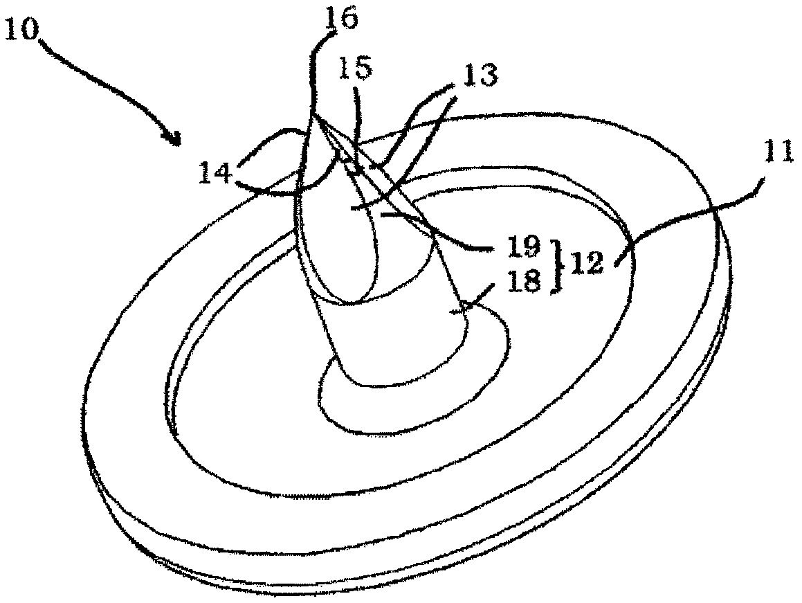
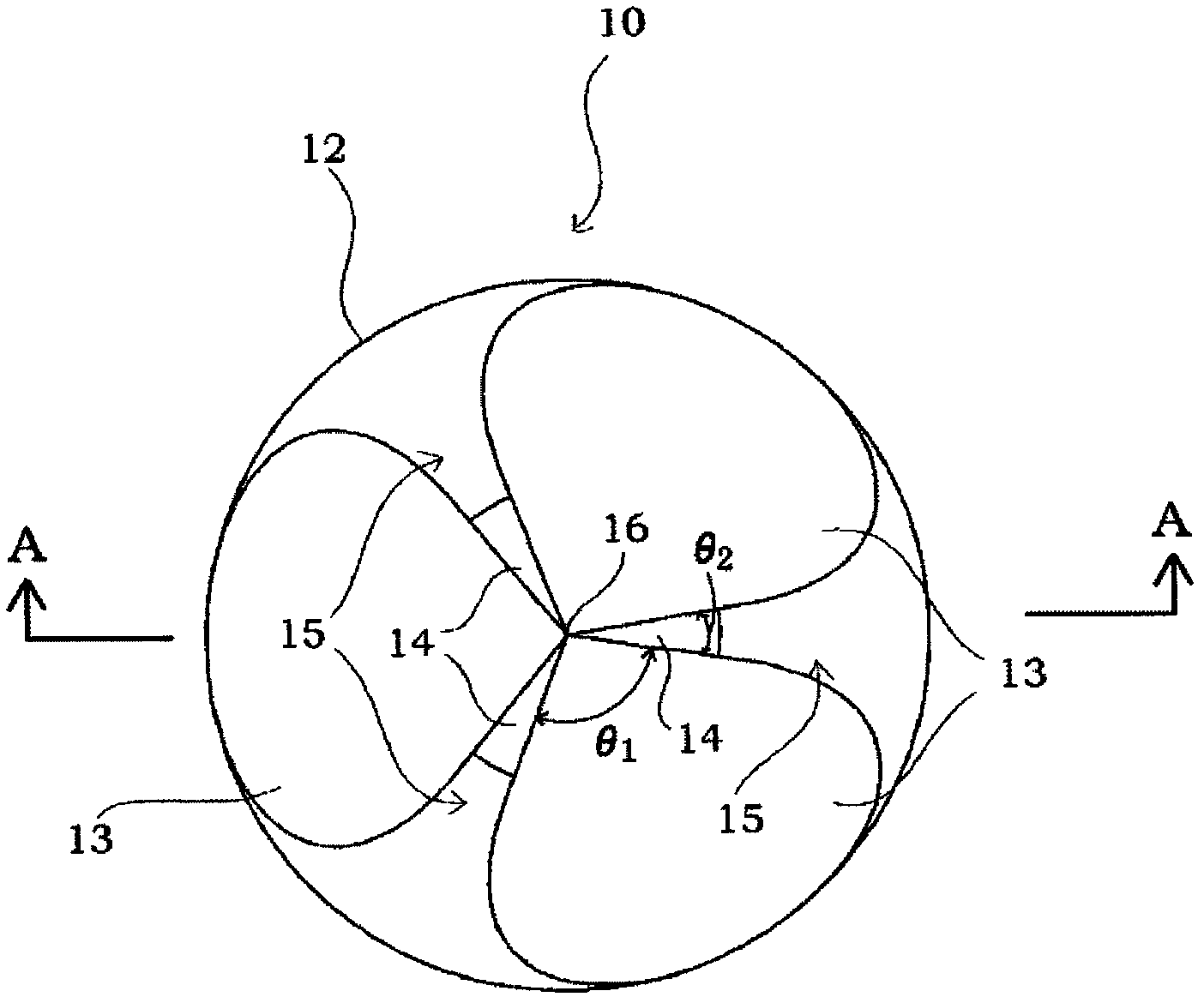
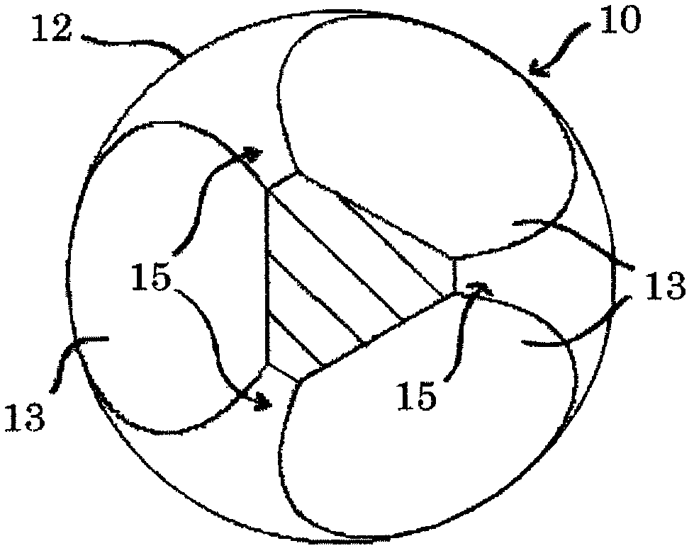
[0048] figure 1 The perspective view which shows the button attachment member 10 which concerns on 1st Embodiment. figure 2 It shows the top view of the post part 12 of the button attachment member 10. image 3 Indicates the column portion 12 of the button mounting member 10 Figure 4 The B-B horizontal section view. Figure 4 Indicates the column portion 12 of the button mounting member 10 figure 2 A-A cutaway view. Figure 5 A cross-sectional view showing the button attachment member 10 , the flexible base material 40 , and the female snap body 20 before the column portion 12 is inserted.

[0049] The female snap 30 has a button attachment member 10 and a female snap body 20 .

[0050] The button attaching member 10 has a base 11 and a post 12 formed so as to stand up from the approximate center of the surface of the base 11 and used to penetrate a flexible base material 40 such as cloth or the like of clothing. The ...

no. 2 approach

[0071] The button attachment member is not limited to the configuration described in the first embodiment, and may be, for example, a configuration related to the second embodiment described below.

[0072] Figure 10 It shows the top view of the post part 52 of the button attachment member 50 which concerns on 2nd Embodiment. Figure 11 A cross-sectional view showing a column portion 52 of the button attachment member 50 according to the second embodiment.

[0073] The button attaching member 50 has a base (not shown) and a post 52 formed so as to stand up from a substantially central portion of the surface of the base for penetrating flexible substrates such as clothing. The base is formed in a plate shape such as a substantially circular shape or a substantially rectangular shape, for example. The column portion 52 has a column body portion 58 extending from the base surface and a column top portion 59 extending from the front end of the column body portion 58 in a directio...

no. 3 approach

[0080] The button attachment member is not limited to the structures described in the first and second embodiments, and may be, for example, the structure of the third embodiment described below.

[0081] Figure 12 It shows the top view of the post part 62 of the button attachment member 60 which concerns on 3rd Embodiment. Figure 13 It shows the front view seen from the front of the rib part 65 of the post part 62 of the button attachment member 60 which concerns on 3rd Embodiment. Figure 14 It shows the front view seen substantially from the front of the 1st inclined surface 63 of the post part 62 of the button attachment member 60 which concerns on 3rd Embodiment.

[0082] The button attaching member 60 has a base (not shown) and a post 62 formed so as to stand up from a substantially central portion of the surface of the base for penetrating flexible substrates such as clothing. The base is formed in a plate shape such as a substantially circular shape or a substantia...


PUM


Abstract

A button mounting member (10) is equipped with a base (11, 71) and a columnar post (12, 52, 62, 72) formed to stand upright on the surface of the base (11, 71). The columnar post (12, 52, 62, 72) is equipped with a post barrel part (18, 58, 68, 78) extending from the surface of the base (11, 71) and a triangular cone-shaped post top part (19, 59, 69, 79) extending from the post barrel part (18, 58, 68, 78). The post top part (19, 59, 69, 79) is provided with three first inclined surfaces (13, 53, 63, 73) that form the three side surfaces of the triangular cone, and second inclined surfaces (14, 54, 64, 74) that are inclined toward the tip and are formed on ridge parts (15, 55, 65, 75) between the adjacent first inclined surfaces (13, 53, 63, 73).

Description

technical field [0001] The present invention relates to a button attaching member attached to a flexible substrate such as cloth for clothing, or a resin sheet for making a bag or a box. Background technique [0002] Generally, a female snap button has a button installation member and a female snap button main body, or a male snap button has a button installation member and a male snap button main body, and the button installation member has an upright column portion; The insertion opening for the post of the button mounting member to be inserted or the main body of the male snap button is formed with an insertion port for the post of the button mounting member to be inserted; the post of the button mounting member is made to penetrate flexible substrates such as cloth of the clothes, and the The column part is inserted into the insertion opening of the female snap button main body or the male snap button main body provided on the opposite side of the flexible base material,...

Claims


Application Information

Patent Timeline
Patent Type & Authority Applications(China)
IPC IPC(8): A44B1/42A44B1/18A44B1/28A44B17/00
CPCA44B1/44A44B17/0005
Inventor 长谷川建二铃木和彦杉山裕之
Owner YKK CORP
Why Eureka
Try Eureka